low power ionic air reverse engineering problem

Thread Starter

BB Kid

Joined Aug 22, 2017
10
Hi all,

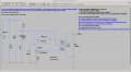
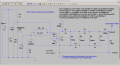
I bought a very small low power high voltage generator from that online auction place. I want to use it for a different purpose, so I traced out the schematic on paper. It didn't look right, so I double checked my schematic, I don't think I made any errors. So, I tried to simulate it in LTSpice. And, it shows no sign of life-all the nodes have nothing but steady state DC on them.

For the life of me, I can't figure out how the thing works by using LTSpice!

However, in real life, the unit runs great, producing about 200 volts DC (RMS).

In LTSpice, I changed the value of some components and boosted the supply voltage, nothing I did makes the simulation show the slightest signs of life!

I posted the schematic from an LTSpice screen capture. I'd like to run the thing in LTSpice if possible.

Any suggestions appreciated.

TY

BB


air purifier screen capture.png
 

Thread Starter

BB Kid

Joined Aug 22, 2017
10
I just realized that some users might have LTSpice, so here is the netlist.

But, the forum won't let me attach the netlist due to its filetype (I think).

Here's the contents of the netlist.

"ExpressPCB Netlist"
"LTspice XVII"
1
0
0
""
""
""
"Part IDs Table"
"F0" "10" ""
"R2" "4.7k" ""
"R5" ".51" ""
"C0" ".01µ" ""
"LED" "STW8B12C" ""
"Q1" "2N2222" ""
"C5" ".03µ" ""
"C7" "100µ" ""
"L1" "100µ" ""
"L2" "100µ" ""
"L3" "10m" ""
"V1" "5" ""
"C1" ".001µ" ""
"R6" "1k" ""
"R1" "20Meg" ""
"Net Names Table"
"N001" 1
"N002" 4
"N004" 9
"N003" 12
"N007" 17
"0" 19
"N005" 26
"N006" 28
"output1" 30
"Net Connections Table"
1 1 1 2
1 4 1 3
1 12 1 0
2 1 2 5
2 5 1 6
2 8 1 7
2 9 2 8
2 10 2 0
3 2 1 10
3 7 2 11
3 9 1 0
4 2 2 13
4 6 1 14
4 7 1 15
4 13 2 16
4 14 1 0
5 3 1 18
5 6 3 0
6 3 2 20
6 4 2 21
6 8 2 22
6 11 2 23
6 12 2 24
6 13 1 25
6 15 2 0
7 5 2 27
7 14 2 0
8 6 2 29
8 10 1 0
9 11 1 31
9 15 1 0

I did have a more closer look at the simulation, a few of the current paths show a partial sinewave starting at T=0. They quickly degrade into dc though. If I extrapolate the partial cycle, it appears to be about 8 microseconds long, corresponding to 125 KHz. That's probably a higher frequency than it should be, but my extrapolation is not precise::>

TY to all.

BB
 

Thread Starter

BB Kid

Joined Aug 22, 2017
10
I found an error with R6, it goes to ground!! The diagram now looks much better after the change, it looks like it should work.

However, there is still no sign of any oscillation, just constant DC everywhere!

Here is the corrected schematic (screen capture from LTSpice, the corrected netlist and a photo of the printed circuit board.

Sure wish someone has suggestions.

TY

BB


"ExpressPCB Netlist"
"LTspice XVII"
1
0
0
""
""
""
"Part IDs Table"
"F0" "10" ""
"R2" "4.7k" ""
"R5" ".51" ""
"C0" ".01µ" ""
"LED" "STW8B12C" ""
"Q1" "2222-hibeta" ""
"C5" ".03µ" ""
"C7" "100µ" ""
"L1" "100µ" ""
"L2" "100µ" ""
"L3" "10m" ""
"V1" "5" ""
"C1" ".001µ" ""
"R6" "1k" ""
"R4" "20Meg" ""
"Net Names Table"
"N001" 1
"N002" 4
"N004" 9
"N003" 12
"N007" 16
"0" 18
"N005" 26
"N006" 28
"output" 30
"Net Connections Table"
1 1 1 2
1 4 1 3
1 12 1 0
2 1 2 5
2 5 1 6
2 8 1 7
2 9 2 8
2 10 2 0
3 2 1 10
3 7 2 11
3 9 1 0
4 2 2 13
4 6 1 14
4 7 1 15
4 13 2 0
5 3 1 17
5 6 3 0
6 3 2 19
6 4 2 20
6 8 2 21
6 11 2 22
6 12 2 23
6 13 1 24
6 14 1 25
6 15 2 0
7 5 2 27
7 14 2 0
8 6 2 29
8 10 1 0
9 11 1 31
9 15 1 0
 

Attachments

Bordodynov

Joined May 20, 2015
3,180
Download your schema for LTspice. I do not want to do it (draw a new one) using your drawing. I think that I will preach it so that it will function. I already see that one of the inductances needs to be rotated 180 degrees.
 

Thread Starter

BB Kid

Joined Aug 22, 2017
10
The forum is telling me my message is to large to process, so I can't upload anything, even though I trimmed everything from the message. Hope this works.

OK, ty.

I did try changing the inductor phasing marks, neither one worked, so I put it back to the default. It looks suspicious to me too::>

Heres the LTSpice file and the MS8050 datasheet.

I used a 2N2222 because I couldn't resolve the issue with the datasheet, so it's possible the issue is to little or to much transistor gain.

Thanks so much for lending a hand, this thing has been driving me batty::>

Also....

There is also some ambiguity with the transistor marked A3Y. The problem is that there is a PNP and an NPN that both use that marking. One is an MMS9012 PNP, the other is an MS8050 NPN. They also both have different pin outs. I checked the transistor on the PCB, and it appears to be an NPN. However, with the base and collector reversed, the collector now goes to one of the end terminal of the transformer, which looks much more correct to me. So, I think it should be an NPN with the collector and the base terminals reversed from the datasheet pinout given.

Here's the files....I had to divide my message up into 2 parts to shorten the message up.
 

Attachments

Last edited by a moderator:

Thread Starter

BB Kid

Joined Aug 22, 2017
10
I am in your debt, many thanks. I was unaware that the a3y was the vendor and package code!!!!

Seeing those -900v spikes is most sobering, and dramatically illustrates the importance of a minimum load resistance across a high voltage generator output such as this.

The cockcroft-walton multiplier(s) should be a significant load all by itself, I'll add the rest of the circuit and retest.

I'm curious, where did you find the model for the 8050 transistor. I looked for it briefly and never managed to find it.

I should have gone with my instinct instead of depending on spec sheets!

Again, many thanks.

BB
 

DickCappels

Joined Aug 21, 2008
10,186
I think there is an error in the schematic.

If you move C5 and R2 to the opposite leg of the transformer so they are in series with the base instead of the collector you will probably find you can get a lot more power out of it.
 

Thread Starter

BB Kid

Joined Aug 22, 2017
10
If you move C5 and R2 to the opposite leg of the transformer so they are in series with the base instead of the collector you will probably find you can get a lot more power out of it.[/QUOTE said:
Hi Dick,

It looks to me like R2 and C5 are already in series with the base.

The circuit is truly anemic in terms of output power though! But, the input current from the simulation agrees with the approximate current draw from the actual hardware (as measured by others). And, the transformer is microsized, it is less than 1cM L, W and H. So it might not tolerate more output current. It might not be able to supply much more power than it is already. The transformer is so small that the circuit with electrolytic cap, LED and transformer actually fits inside a slightly oversized USB flash drive enclosure. I'll run it for awhile tomorrow (inside the enclosure) and see how hot the transformer gets.

I did add the Cockcroft-Walton voltage multiplier circuit into the simulation, and while testing it, I realized the output voltage rises forever, with voltages well in excess of 1kV and still rising after 4 seconds of simulation time. And, if I load the output with enough resistance to limit the output voltage to a safe value, the circuit only produces a few microamps of current for the actual load. I think this is a design error, once the output reaches a certain level, the oscillator needs to shut down.

And, it looks like R4 isn't needed at all when the voltage multiplier is added to the simulation. It's there to present a minimal load, but the caps and diodes from the CW multiplier assembly already presents a significant load all by themselves.

I'll upload the full LTSpice .asc file and a screen capture showing the schematic when I can-it might not be until tomorrow morning however, I need my beauty rest::>

Regards,

BB
 
Top