Low duty cycle at primary of pulse transformer

Thread Starter

Simranjit

Joined Apr 16, 2024
33
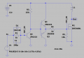
Hi, I am a trying to switch a pulse transformer (hand wound with multiple taps at primary, currently testing with roughly 70 turns give or take) with IRF540n at 230kHz. The duty cycle at gate of MOSFET is around 49%. The duty cycle at OUT (primary of transformer) is 26%. The secondary winding shows a little noise when signal switches to low. I have attached the picture of:
schematic,
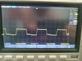
signal at gate of mosfet,
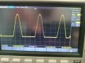
signal at primary,
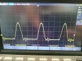
signal at secondary and
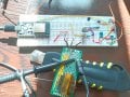
breadboard circuit.
Please let me know how I can improve this circuit. Like improve duty cycle at primary as close to 49% as possible.
 

Attachments

MisterBill2

Joined Jan 23, 2018
19,626
The electronic Tesla coils are power oscillators with a resonant secondary winding. I am not sure where a pulse transformer fits into that picture. The output pulse falls to zero when the core of the pulse transformer becomes saturated. And the time for it to become saturated is based on current and time. So the pulse width out of a pulse transformer is sharply defined.
 

Ian0

Joined Aug 7, 2020
10,293
How are you resetting the flux to the pulse transformer? If you don't bring the flux back to zero it will saturate. If the power supply is overloaded and shuts down at that point, it will appear that the duty cycle is reduced.
You seem to have built half the circuit in you reference: it needs the other half to keep the flux balanced.
 

Thread Starter

Simranjit

Joined Apr 16, 2024
33
How are you resetting the flux to the pulse transformer? If you don't bring the flux back to zero it will saturate. If the power supply is overloaded and shuts down at that point, it will appear that the duty cycle is reduced.
You seem to have built half the circuit in you reference: it needs the other half to keep the flux balanced.
Thank you for your reply. I'm trying to learn more about transformers. I apologize if I'm wrong. I was using wrong kind of core material. I was trying to build gate drive transformer with someone unknown material (my guess it was MnZn). I really thought I could do it. Mostly on Internet people say you need 8 turns on primary for GDT. I was using 70. Regarding the keeping the flux balanced I guess you are right. When drain goes to primary tries to dip further than zero. I think it was indication that I needed to provide negative half of wave also. I found some nice tutorial which lists all materials I can use here. https://highvoltageforum.net/index.php?topic=1854.msg13949#msg13949
 

Thread Starter

Simranjit

Joined Apr 16, 2024
33
The electronic Tesla coils are power oscillators with a resonant secondary winding. I am not sure where a pulse transformer fits into that picture. The output pulse falls to zero when the core of the pulse transformer becomes saturated. And the time for it to become saturated is based on current and time. So the pulse width out of a pulse transformer is sharply defined.
Hi, I was trying to build a gate drive transformer to isolate control circuitry from from power mosfets. I was using wrong kind of material MnZn (I guess). I think I got confused between naming terminology.
 

Ian0

Joined Aug 7, 2020
10,293
Every transformer has a parameter called "Voltage Time product". If ∫Vdt exceeds that figure the transformer will saturate.
Obviously, if V is always positive, ∫Vdt will tend to infinity, so the VT product is soon exceeded.

VT is increased by increasing the number of turns or by increasing the cross sectional area of the core.
For a transformer which is driven from a bipolar voltage (A square wave that goes both positive and negative) then the VT product is V/(4.f.Ae.Bmax) where f is the frequency, Ae is the cross-sectional area and Bmax is the maximum flux density (about 0.2T for ferrite).
 

MisterBill2

Joined Jan 23, 2018
19,626
Usually when I switch off the current the magnetic field collapses. Not instantly, but soon enough. Of course that means selecting a core material that does not tend to become permanently magnetized.
 
Top