Low Battery Disconnect

Status
Not open for further replies.

Thread Starter

tazntex

Joined Sep 29, 2008
27
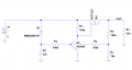
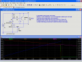
I have I circuit that I built and it is powered by a 9v battery. On the board I am using a LP2950 5v regulator TO-92 package. I would like to turn off the battery when the voltage falls to 7.5V. I have been experimenting with a 7.5V zener, cathode attached to the the positive terminal on the battery, the anode to a 1.2k resistor and that same resistor connected to the base of a 2N3904 transistor. The collector of the 2N3904 connects to the ground leg of my LP2950 regulator, the emitter connects to battery ground. This seems to work but instead of turning the transistor off instantly, it is cycling the power on/off until finally the battery is disconnected. I have very little landscape on the PCB to work with so I am trying to keep this as small as possible.

Any suggestions?

Thank you
 

SgtWookie

Joined Jul 17, 2007
22,230
No, it's not. It is required to be closed momentarily when the battery is replaced. Otherwise, the Vgs of U1 will stay at 0v, preventing any current flow to your load.

In the simulation, it never actually closes; it's simply two disconnected wires. But it won't work unless the gate is pulled high momentarily to provide a ground path for Q1's biasing circuit (the Zener and resistor)

Now that I think about it a bit more, a small capacitor (say, 10nF) across Q1 would likely provide the same functionality without having a physical switch.
 

Thread Starter

tazntex

Joined Sep 29, 2008
27
SgtWookie,
Thanks for the circuit and I have carefully assemble this according to your schematic, for the disconnect it seems to work great. When I replace the battery with a fresh one, it still does not start. I can short C1 and then it will start up. I've tried adding an additional parallel 10nF to C1 to bring it down to 5nF but no sucess. Any suggestion?

Thank you very much for your time.
 

SgtWookie

Joined Jul 17, 2007
22,230
I forgot about "contact bounce". When you replace the battery, the power is actually connected and disconnected many times in rapid succession, even though it seems instantaneous to you.

The "quick fix" is to replace C1 with a momentary normally-open switch.
 

Thread Starter

tazntex

Joined Sep 29, 2008
27
If I place a 1M resistor across C1 then it will restart with a fresh battery connected. When I change the new battery to one with about 6.76Vrms the circuit does not come on which is good. So, since I can't use a switch on this will the 1M resistor work or what would you recommend?

Thanks again.
 

SgtWookie

Joined Jul 17, 2007
22,230
Interesting. If placing the 1M resistor across C1 works, then do so. :)

I'd planned on the 2N3906's leakage current to take care of the cap discharge over time; apparently your particular 2N3906 has extremely low leakage.

The 1M resistor will have a 6.6nA or less current flowing through it when the battery gets cut off by the MOSFET, which will eventually completely discharge the battery.
 

Thread Starter

tazntex

Joined Sep 29, 2008
27
With the 6.6nA drain after the circuit turns off would not really matter since the purpose is to protect the circuit being powered by the 9V battery so other than just draining the battery since it needs to be replaced with a fresh battery would be ok, right?, or am I wrong?

Thanks again
 

SgtWookie

Joined Jul 17, 2007
22,230
It'll be OK, if the battery isn't left in the unit indefinitely after the battery gets cut off.

Completely discharged batteries seem to leak more quickly than those that still have some charge left in them.
 

Thread Starter

tazntex

Joined Sep 29, 2008
27
"Is your 7.5V threshold critical?"
I am using a LP2950 5V regulator to power a 16F628A. Although I have the brown out detect on, I thought it would be best to protect the rest of the circuit if the voltage being applied to the regulator drops below 8 volts. So if I understand the LP2950 data sheet minimum input voltage 6V, seems like I read somewhere once it was always better to have 4 volts more than the output that is to be regulated. Anyhow, I hope this make some sense.

Thanks
 

Ron H

Joined Apr 14, 2005
7,063
SgtWookie, could you design the circuit to have a few hundred mV of hysteresis, instead of maximum? I think the circuit would then recover from the installation "bounce", and still not oscillate when the battery is near the threshold.
 

eblc1388

Joined Nov 28, 2008
1,542
So if I understand the LP2950 data sheet minimum input voltage 6V, seems like I read somewhere once it was always better to have 4 volts more than the output that is to be regulated. Anyhow, I hope this make some sense.Thanks
No, this does not make sense. What you read is true for regulator like 78xxx but not modern LDO regulator.

The LP2950 datasheet spec said its dropout voltage is 0.38V typical and only 0.6V worst case, one should really design for 0.6V dropout allowance. Allowing more just means you have to shutdown you PIC earlier for no useful purposes.

Your circuit will continue to work fine with 5.6V input to the LP2950. This is what LDO voltage regulator are for.
 

Thread Starter

tazntex

Joined Sep 29, 2008
27
Thanks for clarifying the voltage in to the regulator. I'll sleep better knowing that. Ya'll are great, thanks to all for your help.
 

j4e8a16n

Joined May 1, 2013
44
This circuit works. I putted three 6000uF caps (positive at positive zener side, negative to ground) for surge currents demand (like a motor) which would temporaryly lower the voltage.
Thanks
 

#12

Joined Nov 30, 2010
18,224
The original poster of this thread has not been logged in for over 2 years. However good your advice, he will probably never see it.
 
Status
Not open for further replies.
Top