Lost on Sequential Start Control

Thread Starter

imajica

Joined Mar 16, 2017
6
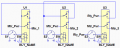
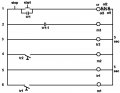
This is my circuit so far, what it needs to do now is: If motor 3 is not running, motor 2 & motor 1 will not run. If motor 2 is not running, motor 3 may run, but motor 1 will not run. If motor 1 is not running, motor 2 & motor 3 may run.

I don't have a clue how to accomplish this...Pg 463.jpg
 

Attachments

MaxHeadRoom

Joined Jul 18, 2013
30,660
Is this a PLC circuit or hardwired, if PLC you can use any output as a contact (boolean) function as many times as you wish, if hardwired, then relay contacts can be added.
BTW, if this is a hardwired circuit, it is now considered bad form to place the O/L's on the neutral or neg side of the motor coil, it is considered a safety issue.
You may see it in the following examples but not recommended.
Telemecanique wiring diagrams
Max..
 
Last edited:

JoeJester

Joined Apr 26, 2005
4,390
Not yours. The Thread Starters. His drawing doesn't match his words. I know you are fully capable of explaining your drawings.

I'm interested in his 5 sec TD relays. Plus his wiring certainly doesn't match the wording. So, I wanted him to explain his control circuit from zero to all three motors running.
 

tranzz4md

Joined Apr 10, 2015
315
I believe his wording is what he wants, and his initial ladder diagram is what he wanted to revise to give him the result that he'd described in words. Ladders are great for relay circuits.

It was never acceptable to install contacts (including motor overloads) between a load and the common, grounded, conductor. Motor overloads were first used and wired to the contactor coil terminal opposite other control logic devices, back when those coils were line voltage, or individual transformers with ungrounded secondaries were used and no grounded conductor was present in the motor starter housing or circuit. 120V AC circuits utilizing a grounded conductor ("neutral") became common about the time the first PCs (programmable controllers) were being introduced, and large, complex control circuits were also becoming commonplace.
 

Thread Starter

imajica

Joined Mar 16, 2017
6
This is an assignment, I have to design a ladder diagram to do the following:
Motor 3 must start 1st.
5 seconds after motor 3 starts, motor 2 starts.
5 seconds after motor 2 starts, motor 1 starts.
If motor 3 is not running, motor 2 & motor 1 will not run.
If motor 2 is not running, motor 3 may run, but motor 1 will not run.
If motor 1 is not running, motor 2 & motor 3 may run.
An overload on any of the motors will shut down all 3 motors.
Pressing the stop button stops all motors.
 

MaxHeadRoom

Joined Jul 18, 2013
30,660
This is an assignment, I have to design a ladder diagram to do the following:
Motor 3 must start 1st.
5 seconds after motor 3 starts, motor 2 starts.
5 seconds after motor 2 starts, motor 1 starts.
If motor 3 is not running, motor 2 & motor 1 will not run.
If motor 2 is not running, motor 3 may run, but motor 1 will not run.
If motor 1 is not running, motor 2 & motor 3 may run.
An overload on any of the motors will shut down all 3 motors.
Pressing the stop button stops all motors.
It will be done differently for PLC ladder and hardwired version, state which.
This will decide whether extra components such as aux relays are needed.

It was never acceptable to install contacts (including motor overloads) between a load and the common, grounded, conductor.
It may not have been acceptable but it was, and to some extent in some areas, still a practice, This was customary going back some decades.
I no longer have the safety sheet issued to warn of the down side of the practice, but it was probably about 20years ago.
One of the main reasons I was given that when stop/start units were wired it was easier for some reason when wiring the coil, supposedly saved a connection.
Max.
 

Thread Starter

imajica

Joined Mar 16, 2017
6
It will be done differently for PLC ladder and hardwired version, state which.
This will decide whether extra components such as aux relays are needed.


It may not have been acceptable but it was, and to some extent in some areas, still a practice, This was customary going back some decades.
I no longer have the safety sheet issued to warn of the down side of the practice, but it was probably about 20years ago.
One of the main reasons I was given that when stop/start units were wired it was easier for some reason when wiring the coil, supposedly saved a connection.
Max.
 

MaxHeadRoom

Joined Jul 18, 2013
30,660
I assume you can use aux relays as needed?
Although M1,M2,M3 would be assumed to be contactors which would normally posses aux contacts.
TR1 & TR2 are running unconditionally right now. Did you add these?
Max.
 

MaxHeadRoom

Joined Jul 18, 2013
30,660
How are you making out?
I don't really see the need for timers.
The other question is the whole process initiated by the single start P.B.?
If so there will only be one possible sequence.
Max.
 

Thread Starter

imajica

Joined Mar 16, 2017
6
The timers are there because:
5 seconds after motor 3 starts, motor 2 starts.
5 seconds after motor 2 starts, motor 1 starts.

Yes, the process is started w\ the start button.
 
Top