 Facebook
 Google
 GitHub
 Linkedin
Hi everyone,
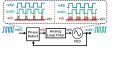
The attached figure shows a simple PLL with its waveforms on each component's output node. Can anyone please tell me why is the output of the analog loop filter, v(t) is the average voltage of the pulses (if my analysis is correct). From my understanding, the loop filter is just a low pass filter which used to filter out the high frequency component from the PFD. How does it actually works?
The attached figure shows a simple PLL with its waveforms on each component's output node. Can anyone please tell me why is the output of the analog loop filter, v(t) is the average voltage of the pulses (if my analysis is correct). From my understanding, the loop filter is just a low pass filter which used to filter out the high frequency component from the PFD. How does it actually works?
Attachments
-
 48.4 KB Views: 60
")


