 Facebook
 Google
 GitHub
 Linkedin
I've been working on a boxing robot for a number of years. It's two human sized robots that you control with a joystick or a Kinect camera (you do a left punch, it does a left punch). Hoping to sell these into arcades.
I've been struggling with the main power board. I'm using large wormgear motors, they use a lot of current at startup (first 1/10th sec) and then it settles down. I don't want to put much of an acceleration ramp in them because I want them to be very quick from a dead stop. But this places a huge load on the power supply (1200W PC power supply at the moment) so I've added in 5 x 2.7V 350F capacitors (70F @ 120V) which seems to be working.
Well yesterday I sent a motor controller up in smoke because one of the motors stalled and current/voltage shot through the roof and as I've now learned 60A slow auto fuses don't pop at 60A. After talking to the motor controller manufacturer (Basic Micro makes the Roboclaw, who is awesome btw, buy stuff from them) we came up with the idea of doing two things. First a voltage clamp on my power board separate from the one built into the motor controller. So if voltage goes above 13V (12V supply) it'll turn on a MOSFET and bleed voltage through a large 50W panel resistor. The second is a similar circuit that might turn on at a higher voltage (maybe 15V?) if the voltage clamp doesn't get things under control. It would turn on a MOSFET that would turn off a large relay, killing all power to the controllers.
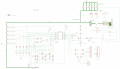
I'm now trying to figure out a good design for monitoring the voltage. I don't have experience with comparators but it seems like I would need two of them, both comparing supply voltage against motor controller voltage (voltage after the diode protecting the power supply). Any suggestions? I've attached the current schematic. On the right side of the schematic you'll see two different mosfets, the top one has nothing connecting to the Gate, that's where I need the circuit.
I'm also thinking if there's a better way to keep the caps balanced, my new design was going to use this TI BQ33100 and some 1A'ish MOSFETs to balance the caps but wouldn't a better solution to be to charge each cap separately with a 2.4V source? Problem is I can't seem to find a good 2.4V constant current 10A voltage source and I'd need 5 of them.
I've been struggling with the main power board. I'm using large wormgear motors, they use a lot of current at startup (first 1/10th sec) and then it settles down. I don't want to put much of an acceleration ramp in them because I want them to be very quick from a dead stop. But this places a huge load on the power supply (1200W PC power supply at the moment) so I've added in 5 x 2.7V 350F capacitors (70F @ 120V) which seems to be working.
Well yesterday I sent a motor controller up in smoke because one of the motors stalled and current/voltage shot through the roof and as I've now learned 60A slow auto fuses don't pop at 60A. After talking to the motor controller manufacturer (Basic Micro makes the Roboclaw, who is awesome btw, buy stuff from them) we came up with the idea of doing two things. First a voltage clamp on my power board separate from the one built into the motor controller. So if voltage goes above 13V (12V supply) it'll turn on a MOSFET and bleed voltage through a large 50W panel resistor. The second is a similar circuit that might turn on at a higher voltage (maybe 15V?) if the voltage clamp doesn't get things under control. It would turn on a MOSFET that would turn off a large relay, killing all power to the controllers.
I'm now trying to figure out a good design for monitoring the voltage. I don't have experience with comparators but it seems like I would need two of them, both comparing supply voltage against motor controller voltage (voltage after the diode protecting the power supply). Any suggestions? I've attached the current schematic. On the right side of the schematic you'll see two different mosfets, the top one has nothing connecting to the Gate, that's where I need the circuit.
I'm also thinking if there's a better way to keep the caps balanced, my new design was going to use this TI BQ33100 and some 1A'ish MOSFETs to balance the caps but wouldn't a better solution to be to charge each cap separately with a 2.4V source? Problem is I can't seem to find a good 2.4V constant current 10A voltage source and I'd need 5 of them.
Attachments
-
 373.8 KB Views: 9
")


