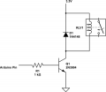
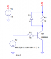
Don't think so. Assuming a 5.0 V output from the Arduino (which it is not), the base current would be 4.4 mA at 1 K, and less than 0.5 mA at 9 K. The 1 K current is ok, but the 9 K current is way too low to assure firm saturation at 50 mA collector current.
At Ic = 50 mA, the 2N3904 has a minimum specified gain of only 60. If you stick to the 10:1 rule of thumb, even the 1 K current is too low. If the Arduino output voltage is only 3.3 V, then both resistor values are off.
The datasheet specifies full enhancement at Vgs = 10 V, so even though it behaves very well at Vgs = 5 V, it is not a true logic level part.
And I know this goes back to the 60's when MOSFETs were extremely delicate, but I'm never comfortable recommending driving an inductor with a FET. I've lived through almost the entire history of FET development, know all of the arguments, and have designed them into a variety of power application. But, still . . .
I have some 2N7000 - are these super old? Their RDS is pretty high.
try the Si2302 or something similar, the RDS is several factors better and will trigger down to 2.5V Vgs with about 100 mOhms Rds… if you need thru hole, look into IRL series… they are overkill but easy to work with.
I agree with generally using a BJT to drive an inductive load, but with the back EMF clamped, it should be fine. I just don't like the thought of wasting 5 mA to drive 50mA. With PMOS, even with a pull down (which in this case you might not need) you can keep it well within 100:1 and if speed is not an issue much lower current. I usually double up with a PMOS on critical use just in case.
Logic level shifter. The same chip is used on a dozen modules available through as many distributors. Nice feature is bi-directional. That assumes you only want to go from 3.3 volts to 5.0 volts or 5.0 volts to 3.3 volts.
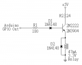
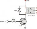
The first picture is driving the relay low side and the other is driving high side. The second is not a desirable configuration. You'd normally use a PNP transistor so you don't lose a diode drop for the coil voltage. Wherever you found the second circuit, I'd suggest avoiding them in the future.
The first picture is driving the relay low side and the other is driving high side. The second is not a desirable configuration. You'd normally use a PNP transistor so you don't lose a diode drop for the coil voltage. Wherever you found the second circuit, I'd suggest avoiding them in the future.
Thanks.
I found that here, actually I prefer first one too, but I soldered a PCB which is not easy to modify, so: https://prometec.org/actuators-and-sensors/arduino-and-relays/
I'll keep your advice.
seems not work. I measured the empty VE (even VB) uo to ~4V, so the control is very unstable. why?
That’s it! This thread went off the rails a long time ago. It’s easy to forget the original problem (I did, although my last post did provide important general information).

 Facebook
 Google
 GitHub
 Linkedin