looking for Circuit Design help

Bernard

Joined Aug 7, 2008
5,784
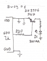
Yes, for LEDs under 100 mA, an extra driver is not needed. The ckt is set for about 50% duty, I think something around 30-70% would be better & would require some changes- another pot & 2 diodes.
Sometime the battery question needs to be settled.
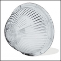
I ran a test on a light, a single bright red LED, " Ball, Quilted Crystal" 8 oz jelley jar, Al. conical reflector, 150Ω, & 4 AA NiMH cells. 360 deg viewing from 300 ft looker good to me.
 

Thread Starter

george0039

Joined Oct 15, 2008
167
Hi Bill

Yes, I would like Three Seperate circuits. With each to turn on at Dusk / Dark - LDR included. Be able to be either set to Flash OR be on constantly by me the user and turned off manually. And a smaller battery source like you suggested. So one circuit / PIC programmed for Each LED.

Thanks Bill

George
 
This circuit can be programmed to flash a single LED < 25mA
The DIP switch would allow for 6 program variations.
To save power when sleeping it could be programmed to wake up on power up or sample daylight every minute or so.
Flashing can be simple or complex like a South Buoy for example.
South buoys flash at the rate of 6 times in 15 seconds followed by a single long flash. A very quick flash can also be used — 6 flashes every 10 seconds plus 1 longer flash at the end of each group to mark the end of 1 flash cycle.
I'm pretty busy doing contract work, I'll try to post code when I can.
 

Attachments

Bernard

Joined Aug 7, 2008
5,784
Sorry, I just had another long senior moment-- now I remember why I added the invertor; if reset state is used to turn on LED, then the day-night function is negated. Let's put the BS 170 back in. Now I'll try to get back to sleep.
 

tracecom

Joined Apr 16, 2010
3,944
Sorry, I just had another long senior moment-- now I remember why I added the invertor; if reset state is used to turn on LED, then the day-night function is negated. Let's put the BS 170 back in. Now I'll try to get back to sleep.
But you are now sinking current instead of sourcing it, so does that invert the function? (I haven't been following the thread closely, so my observation isn't worth much.) You might also consider replacement trailer lenses like this. It's a Grote 90301, but they are available in other colors. Or you might want the entire lamp housing; it should be water resistant.
 

Attachments

Bernard

Joined Aug 7, 2008
5,784
The Grote lens looks possible, but wish the groves were around lens, instead of up n down. Was looking for something similar in Fresnel on linticular; found one from a garden light, 1.5 in. dia X 4 in. tall in lenticular with cone reflector-- but source is unknown to me.
Question: How tall, above water line, is buoy to be, & what is desired visable viewing distance?
 

Thread Starter

george0039

Joined Oct 15, 2008
167
Hi Bernard

The bouy size is about 4 - 5 " tall complete with about a 2" diameter. Approximately. As for viewing, it`s going into a wading pool that has been built for R.C boat use by our local city, 10` max view. Regular LED light with NO extra reflectors are needed.

Please your over designing it. I am Happy with a Good working circuit for each regular LED; Red, Green, Bright White and a good long lasting off the store shelf battery.

Thank You

George
 

Thread Starter

george0039

Joined Oct 15, 2008
167
Hi Blueroomelectronics

In your post #83 in your PIC circuit design, can I ask you, where is the LDR ( dark sensor) to turn the bouy on at dusk / dark then allow me to select either flashing LED OR have it on constantly AND the circuits are for 3 separate LED`s. So 3 separately built circuits by me. For Red, Green, Bright White?

George
A CDS is a type of LDR light sensor. http://en.wikipedia.org/wiki/Photoresistor it's in the schematic, it's the resistor with an arrow through it.
The circuit will support Red Green or White LEDs by simply changing the current limiting resistor. A three position DIP switch has six combinations. The PIC can use it to run different flashing sequences or even simply on could be a combination.

If you want to drive powerful high brightness LEDs you'll need to add a driving transistor e.g. PN2222A
 

Thread Starter

george0039

Joined Oct 15, 2008
167
Hi blueroomelectronics

Thank You for clearing that up for me. How / where would the driving transistor be hooked up into this circuit?

George
 
Last edited:

Bernard

Joined Aug 7, 2008
5,784
A possible driver would use a PNP transistor or logic level p-ch MOSFET. For the 2N3906 ,woulg go up to about 100 mA which could be quite bright.
Question: Do you want alkaline or rechargeable batteries?
 

Thread Starter

george0039

Joined Oct 15, 2008
167
Hi blueroomelectronics

I was wondering if you had a chance to think about how much you would charge me to program a few PIC for me to do what I need from your post 83 circuit? That way I can make 3 seperate circuits on experimentor`s boards so that I have a Red LED, a bright White LED and a Green LED.

So I need at least 3 PIC programmed for now. I just need the PIC from you and have them programmed.

Please let me know Bill

Thanks

George
 
Last edited:
Top