I breadboarded it with a 5V supply; here's what happens in each of the four possible conditions.
1. With pin 4 to Vcc, the LED flashes.
2. With pin 4 to ground, the LED is on constantly.
3. With pin 4 to R4/CDS1 junction and no light, the LED flashes.
4. With pin 4 to R4/CDS1 junction and light, the LED is on constantly.
So if I understand your post, the circuit works BUT not in the dark as it is supposed to with the LDR? The LED should be on at night either flashing or constant by user setting and not on during the day.
So if I understand your post, the circuit works BUT not in the dark as it is supposed to with the LDR? The LED should be on at night either flashing or constant by user setting and not on during the day.
I have edited my post in an effort to make it clearer.
It seems to me that the circuit is performing as you want in conditions 1. and 3., but not in conditions 2. and 4. In conditions 2. and 4., the LED should be off.
But to be honest, I haven't read all the posts in the thread, so I am not certain what you want the circuit to do.
ETA: I will be away from the computer until about 9:00 pm cdt.
OK here is what I wanted. At dusk/night, I want the LDR to detect dark and turn ON the circuit so that either the LED, one for Red, one for Green and one for bright White, three separate circuits , flashes OR stays on continuously by my selection. All to run off of a 9v battery which I can unplug for storage, durability would be nice, ie battery life for several runs etc of nights at 4-5 hours per night etc.
You want three LEDs albeit one at a time flashing for about 4-5 hrs a night.
If it were me I'd use a single button for power (on for 6hrs then auto off) and the same button would cycle through the three LEDs (and off). Again a tiny microcontroller could do this with ease. I'd use 4AA cells for power as they'll give you the longest runtime.
People your not reading my post. I want three separate circuits, one in each bouy. One is Red, one is Green and one is bright white. Each is powered by a 9v and each will be able to be set to Flash or Continuous run by a switch.
OK here is what I wanted. At dusk/night, I want the LDR to detect dark and turn ON the circuit so that either the LED, one for Red, one for Green and one for bright White, three separate circuits , flashes OR stays on continuously by my selection. All to run off of a 9v battery which I can unplug for storage, durability would be nice, ie battery life for several runs etc of nights at 4-5 hours per night etc.
I have been told by tracecom that there is some trouble with the circuit you gave me in the post. Just letting you know and latter in this thread I tried to clear up what I wanted from these circuits.
Not you but others seem to step in without reading what I was after.
So to repeat and after your suggestions, here is what I want:
Circuits that will run off of 9v, One Circuit for a Single RED LED Average type, round. Would be turned on by LDR when it gets dark, would be set to either Flash OR be on constantly by user switch. To turn off circuit by light OR by user, disconnecting battery. So a 2 way toggle switch should be able to switch between flashing and constant on, maybe??
I need one Circuit like this for a RED LED, One for a Green LED and One for a bright White LED. These circuits do not need LONG Battery life since they would NOT be used continuously maybe for a max. of say 8 hours a month if that.
Please I need a parts list if you can for each circuit.
Thanks for the updated circuit and formulas. I have to ask you though, looking at your circuit. I see S1 that controls the LDR / Off / Continuous, so for me to pick the flash rate of the LED I play with different values of R1 & C1 right? Also for the diode CR1(C91) same thing? Can I use a 4004 diode? And to make sure the LDR is a Dark sensitive device so as it gets dark enough the LED comes and shuts off at day time and or being turned off, Right?
George
Too bad a pot could not be used for flash rate adjustments for on and off of the LED ?
It is all or nothing, when there is light it will turn off. I can slow down the response if needed for things like flashlights or lightning, but for now I didn't bother.
R1 is how long the LED stays lite.
R2 is how long between flashes.
You could use a pot for both or either resistor, but you will need another resistor in line with the pot on R1 to keep from accidentally damaging the chip. R1 should not go below 5KΩ for this reason.
C1 interacts with both.
A 1N4004 diode is fine for CR1. Exact type of diode does not matter.
LDRs are pretty simple. Take a ohm meter, you should see 100Ω or so (not critical) in light, several megohms in dark. They don't work any other way.
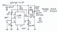
Anothevr version that works well on breadboard. When it is light, CDS-1 pulls pin 4 below .7V holding U1 in reset, pin 3 lo. Pin 3, output, gives proper polarity to keep n-ch fet off, LED dark. When dark, pin 4 goes above .7V, releasing U1 to oscillate, flashing LED. If SW 1 is closed, pin 3 stays hi, LED on. My thought is to use an inverted U ball SW so that buoy could remain sealed while allowing a change from pulse to on. Just a straight ball SW for power as prev. suggested. In the old days we would have used a mercury SW. On current mostly LED current, off = 250 μA. 'Could increase R2 to 5 meg pot with C555. CDS cell goes from about 1k bright light to 1 meg dark.
Thanks for the extra circuit and posting. I am having a little trouble clearly reading ALL of the circuit, could you give me a redraw with clearer labeling?
Also, to be sure, my specs were: use LDR for dark use. at daylight circuit is off. I want to be able to select circuit flashing mode OR constant LED on mode. All run off of 9v. Simple toggle switches I`m ok to use. It would be nice if a pot was included so I could adjust the flashing LED rate.
I need One circuit for a regular RED LED, one for a Regular Green LED and one for a bright white LED. ALL Three circuits with the same operational features.
Could you please explain the switches? S2 makes the LED stay on constantly BUT I am a little confused by S1 - Sensor Off, OFF, daylight Sensor ??
Not sure what that means? What turns the circuit OFF , ON so the LED Flashes etc ??? What changes are needed for a Regular Green LED and a bright white LED ?
Looks like everything is labled, if you see something amis please call it to my attention. The LED & R4 is of your choosing; tried with bright white @ 60 mA & bright red at 25mA. R2 is your frequency pot. Seems to fit all of your specs.
I chose to use a FET driver because of the poor high level drive current of the C555, even at 15 V, only about 10 mA; in addition to the inversion. The BS 170 should be good for 500 mA. Where lines cross, there is no connection. Give a shot at re drawing, might give you a better understanding. Bring on the questions.
Thanks for the fast reply. Just a couple questions after looking at your circuit.
SW1 is that a two position switch, could I use a two position toggle switch there? Also the transistor is that a BS170 / NTE490 and R2 is the adjustable LED flash rate? How do I switch from the LED flashing to being on continuously?
Sorry about bothering you with these questions, just want to make sure I understand it. Also Thanks for your help.
 Facebook
 Google
 GitHub
 Linkedin