 Facebook
 Google
 GitHub
 Linkedin
Hi, I am new to this forum and kind of new to electronics,, I have some basic knowledge, but I think I'm in over my head here and looking for some information on identifying a few components and verifying when I think they are,, this is from an ignition module on a lawn tractor and if I could just fill in the blanks on the last few parts I could rebuild it, a new board is way too expensive for me.
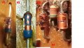
Picture 001 # 1,2 and 3. I believe these all to be zener diodes,two of them have the number eight on them one is blue one is black. Not sure if that has any significance for color change, you would think they would use the same components on the same board. I have not desoldered them yet so I'm not sure if there is a additional number on those or whether 8 stands for the voltage. Additionally the #3 in the photo has 3.0 on it, so I'm assuming it is a 3.0 V zener diode. The #4 photo does not look like a zener diode since it doesn't have the cathode line, so somebody could tell me what this is and how to figure out its value I would appreciate that.
Picture 002, I believe #5 to be some type of film capacitor, the numbers on it have yielded no results in an exhaustive search other than to confuse me more. The 153K could be broken down to a .15pf cap according to one site, but then you have the 100n underneath that which makes me wonder if the value is 100nf, and then what about the voltage.
As for #6, I figured maybe somebody could tell me in advance if these are capacitors or resisters, they seem to be about the same size as a 1 W resistor I know there are additional numbers underneath but I want to try to not to desoldered them until I replace two other resisters that appear to be cracked to see if that will fix the board, however I want to build a board after I test the repair because if I have a major catastrophe with this I won't have a record of all the parts to rebuild it.
The board has a maximum of 14 V in, and controls the coils and I believe the spark advance for the mower, one last thought is most of the resisters are approximately 1/8w between 2 -10% tolerance, I was going to replace all of them with 1/4w 1% tolerance resisters I don't know this is an issue and why they would use multiple tolerances on the board as it seems to just be common sense to use one single type but then again I probably know the least of all the people on this forum, and I'm sure somebody will set me straight with a logical explanation as to why different types are required. Also I'm going to do this on a prototype board so there's no problem with the larger resisters fitting on the board if necessary. I just thought making the components heavier than they were will lead to less failures. Thank you all in advance for any help that you can provide with this, Chuck
Attachments
-
 238.2 KB Views: 15


