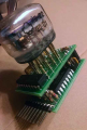
Completely off topic - (should I have started a new thread?) - but what supply voltage and drive circuit did you use for the IV-22s?Use a Serial to Parallel Shift register. That's what I did for my IV-22 clock:
Any I2C Port expander like TCA9535. Note: such expanders can mostly sink about 10..20mA per output but source only some uA (by pull-ups). So use "common anode" configuration for the LEDs.Hello,
I did some googling on this but I'm not even sure if I have my nomenclature correct.
What I would like to do, is control 4 RGB LEDs using I2C from an Arduino Nano because I cannot spare 12 pins just for LED control. I don't need the IC to do any PWM at all, just being able to send it commands over I2C to set pins high or low would be sufficient.
Does anyone know if such a chip even exists?
Thank you,
Mike Sims
I designed it around the actual electrical requirements of the VFDs themselves.Completely off topic - (should I have started a new thread?) - but what supply voltage and drive circuit did you use for the IV-22s?