Looking for a 'typical' solid state 1960's stereo amp schematic for phonographs

Thread Starter

Dale1700

Joined Mar 15, 2019
15
Hello all,

I'm rejuvenating a Zenith portable solid state stereophonic phonograph player. It has no model number or chassis identification, and I haven't been able to find an owners manual with a schematic. I have experience troubleshooting electrical devices. The left amplifier channel works fine so I'm comparing 'like/similar connections' on both R and L channels for voltages, signals, and resistances using an older HP oscilloscope and multimeters. The 4 pots on the bottom of the chassis are for Balance, Volume, Treble and Bass control. It is tedious and time consuming and I'm hoping to acquire a 'typical ' 1960's solid state' stereo schematic that might help reduce the time needed to find the cause of the problem.

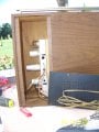
There are two low power 3 lead transistors ( round cans) above the 2nd and 3rd volume and treble control pots about 1/3 of the way up from the chassis bottom. Both these transistors have the audio signal from the phonograph on two leads. No capacitor leakage or burned resistors apparent ....so far. .. indicating that the problem is in the power transistor circuit powering the speakers. The pix's show the right speakers, chassis in the main section of the box, and the underside of the chassis. This pix immediately below shows a similar Zenith with only 3 controls but my guess is that it has the same amplifier as the one I'm working on.

1632928704868.png

Thanks for any help
 

Attachments

Last edited by a moderator:

Thread Starter

Dale1700

Joined Mar 15, 2019
15
Just start at the right speaker and work back until you find something that isn't working.
Thanks for the quick response Dennis. I did start with comparing the power transistors outputs and found the no signal on the right channel. Tracing back is a bit problematic due to the way the components are mounted and the tightness of some of the mounted components. Not impossible and I may have to do it that way.....even if I can get a 'typical' schematic. ..... but I 'd like to get a schematic to refresh my memory of how the controls and components are connected. I'm an old (retired of course) tube type TV repairman from the 60's.
 

MrChips

Joined Oct 2, 2009
30,701
Begin by showing us some clear, well focused photographs of all parts of the system.

1) Show both left and right speaker cabinet internals. There is something that does not look correct with the one posted. It shows a 3-way speaker system with the tweeter wired across the woofer.

2) Show the front controls. We want to know what is each control function.

3) Show the AC power connection to the primaries of the mains transformer and the connections from the secondaries. It appears that the full-wave rectifiers are configured to give negative voltages.

4) Show us closeups of the circuits. In particular, we want to see the markings on the transistors. There are only two transistors showing per channel. There must be more. Where are the power transistors.

5) Show us the phonograph input connections. There need to be RIAA equalization circuitry.
 

dl324

Joined Mar 30, 2015
16,839
Tracing back is a bit problematic due to the way the components are mounted and the tightness of some of the mounted components. Not impossible and I may have to do it that way..
Attach a lead to the probe tip and make an insulated tip to attach to the lead. You're for something to be dead or alive, so any side effects from long leads don't matter.
but I 'd like to get a schematic to refresh my memory of how the controls and components are connected.
You can trace the components and draw one. It's a pain in the arse, but at least you don't have a circuit board that you need to keep flipping over.
 

Thread Starter

Dale1700

Joined Mar 15, 2019
15
Begin by showing us some clear, well focused photographs of all parts of the system.

1) Show both left and right speaker cabinet internals. There is something that does not look correct with the one posted. It shows a 3-way speaker system with the tweeter wired across the woofer.

2) Show the front controls. We want to know what is each control function.

3) Show the AC power connection to the primaries of the mains transformer and the connections from the secondaries. It appears that the full-wave rectifiers are configured to give negative voltages.

4) Show us closeups of the circuits. In particular, we want to see the markings on the transistors. There are only two transistors showing per channel. There must be more. Where are the power transistors.

5) Show us the phonograph input connections. There need to be RIAA equalization circuitry.
Hi Mr.chips

I'm not sure I'm doing this right...I've not tried ever quoting and I'm on a learning curve with this forum. But here are some answers.

1. The left and right speaker boxes are the same so I didn't feel it necessary to post both. The capacitor connected I believe is sort of a simple 'crossover' network.
2. There are 4 controls as show by the 4 pots stems protruding from the bottom of the chassis pix They control Loudness, Balance, Treble and Bass. The pix in the email text is misleading.....my bad.... I used it instead of the actual phono I have. I did mention in my email text that the pix in the text ( not the attachments) was 'similar to what I had. Sorry for the confusion.
3. I don't think my phono has a transformer to convert the 120vac to a lower voltage. The two transformers on the chassis I believe ( subject to closer exam) are part of the audio driving the output power transistors.... I'll have to trace the wire to be sure.
4. Next time I take out the chassis, I plan to try to get any identification marks on them and take some more pix...at least the top of the chassis.. There are 4 power transistors mounted on the top part of the chassis, probably using the chassis as a heat sink.
5. The phonograph leads coming into the chassis are really hard to see....but I'm sure I can find them with more detailed inspection.

I set up my inspection on my patio since I have limited space in my retirement home. Had to put the phono back together after I took the pix and put it back in the garage.. I have a smaller, older, solid state HP o'scope to use and don't have to try to see if my Tektronix 545 would help trace the audio through the chassis.

bertus: I'll give that site a shot. Thanks
 

dl324

Joined Mar 30, 2015
16,839
I'm not sure I'm doing this right...I've not tried ever quoting and I'm on a learning curve with this forum.
When you highlight text with the mouse, you'll be given the option of quoting or replying. If that's the only text you want to quote in your reply, select reply. If you want multiple quotes, select quote, and repeat until you've selected everything you want to quote. Then go to the text entry box and click on the insert quotes button that's under the left side of the text entry box.

I'm using the old blue interface. The new one might have things rearranged...
 

Thread Starter

Dale1700

Joined Mar 15, 2019
15
I'm taking some more time to examine the chassis and box today. I found a sticker p about 3/4 by 3/4 inches with the model number and serial number.......Model Number is X-560-W with a serial number 9417. Nothing on the chassis. That may be useful in getting the exact schematic ... but the Model SA55 is very interesting helpful. Thanks MrChips.

Here's some identification info on some of the components:
2 ... ;xformers : 32-16582; 6D65, 892626 ....6 leads the red and green apparent primaries
4 .... power output xsistors : RCA 36729 FJ 67 or 79 ........ could be I read it upside down
2 ... smaller xsistor cans 980, GC 1696
2 ... smaller xsistors RCA 6598 one lead connected to the green lead of the xformer

Attached are pix of the top of the chassis and the record changer.

I started to draw sketch some wiring but I think I'll try measuring some voltages and see if there is a power transformer inside the record player compartment. the whole unit weighs about 40 pounds.
 

Attachments

MrChips

Joined Oct 2, 2009
30,701
I would like to know how many transistors there are per channel.

I am going to assume the following for each channel as far as I can tell.

#1 - pre-amp, GC 1396 ?
#2 - pre-driver ?
#3 - driver, GC 1696 ?
#4 - output pair of push pull, RCA 36729 (2 transistors TO-3)
 

Thread Starter

Dale1700

Joined Mar 15, 2019
15
MrChips ....as far a s I can tell now, 6 transistors per channel. However, after looking at the youtube video ( once so far) I got the impression that there might be another one buried beneath some of the tightly bundled components in the chassis.

bertus: that video is great! Now I know lots more about the record player ...and where the power transformer is.
 

MrChips

Joined Oct 2, 2009
30,701
As far as I can see the MPS90 schematics I posted matches exactly that of X560.
The transistors that I labelled as pre-driver are in small black plastic packages hidden below the capacitors.

Zenith X560_transistor2.jpg


Zenith X560_transistor1.jpg
 

schmitt trigger

Joined Jul 12, 2010
868
The only thing that I can add to the excellent advice so far;
A stereo amplifier which has one channel working correctly is a tremendous help.
Both channels should be identical, and therefore with a multimeter read the DC voltage around a transistor on the working channel, then go to the opposite channel and check the same transistor.
Start from the input and work your way towards the output.
When you find a discrepancy then you have found the defective circuit section.
 

MrChips

Joined Oct 2, 2009
30,701
You have a very good chance of finding the fault.

1) We have matching schematics with test voltages (and it is clear to read).
2) All the components are discrete and should be readily available (except for obsolete germanium transistors!).
3) The stages are AC coupled.
4) One channel is working.

Let us know if you need help.
 

Dodgydave

Joined Jun 22, 2012
11,284
I would start by measuring the voltages at the transistors and compare them, if you have a scope even better compare the signals at the transistors inputs and outputs...
 

MrChips

Joined Oct 2, 2009
30,701
There are 5 transistors per channel.

With no record playing, set bass, treble, balance to mid-position.
Set loudness to lowest position,

Go through systematically and measure the voltage at C-B-E at each transistor, with respect to GND. Show the sign of the reading.

________LEFT_________RIGHT______

#1 C
#1 B
#1 E

#2 C
#2 B
#2 E

#3 C
#3 B
#3 E

#4a C
#4a B
#4a E

#4b C
#4b B
#4b E
 
Top