Looking for a schematic of a led chaser circuit.

Homebrew1964

Joined Nov 22, 2024
289
Configure the 555 an astable multivibrator with a high duty cycle. The buffer the voltage on the timing capacitor with an emitter-follower and have that drive four resistive voltage dividers, each of which drives the base of one of the switching transistors. Select the voltage divider ratios to give the desired turn-on times. If component selection is done carefully, you can even eliminate the buffer transistor.
A schematic would have been useful.
 

WBahn

Joined Mar 31, 2012
33,047
You can also do it with the 555 as the only IC along with the five transistors and eight resistors (not counting the current-limiting resistors for the LEDs themselves or the bypass capacitors and timing resistors for the 555).

Configure the 555 an astable multivibrator with a high duty cycle. The buffer the voltage on the timing capacitor with an emitter-follower and have that drive four resistive voltage dividers, each of which drives the base of one of the switching transistors. Select the voltage divider ratios to give the desired turn-on times. If component selection is done carefully, you can even eliminate the buffer transistor.

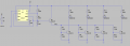
This is crude, but unless a level of accuracy/precision is needed that is not apparent from the description the TS gave, it should work fine.
Here's a circuit thrown together real quick just to show the rough idea.

1781848949890.png

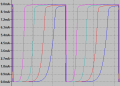
This results in the following currents in the LEDs:

1781849054592.png

The period with these 555 timing components as a period of about 1.2 seconds.

I tried to quickly get the switching times about evenly spaced using standard resistor values. Pots could be used to tweak things as close as you want.

Notice the soft turn-on, particularly for the later LEDs. This may or may not be acceptable. Since the TS stated that they want each transistor to drive multiple LEDs (without giving any indication of how many or what the total current is), one approach to improve things would be to use Darlingtons for the switches. However, with Vcc of 5 V, this will start encroaching on the bottom of the capacitor voltage. The Vcc probably need to be at least about 7 V to prevent this. However, with Darlingtons, the use of the buffer transistor probably isn't needed. If I get a chance, I'll reconfigure for that case and see what it looks like.

Note that I'm not recommending this as a good approach, it is merely an example of one approach that is at the more primitive level of circuitry. It would be very easy to replace the 555 with a simple sawtooth generator circuit, particularly since the sawtooth doesn't have to be very good since the resistor values in the dividers can be tweaked to compensate. I might play with that as well, if I find time.
 
Last edited:

MisterBill2

Joined Jan 23, 2018
27,903
I suggested the CD4018 because that IC has outputs that EXACTLY MATCH the TS requirement statement!
Certainly other schemes wil also work, BUT every one of them is more complex AND many of them require adjustents.
I realize that the CD4018 is less common, and is probably not listed in most hobby-class sales sheets, BUT, take a look at the operation! The match is exactly what the TS requested!
 

schmitt trigger

Joined Jul 12, 2010
2,165
Fully agree with you MB.
Yours is the most straightforward suggestion. Full stop.
Having said this, we all greybeards here like to give our two yen worth of opinion.
The resulting submissions range from the ridiculous to the sublime, but it is a display of the diversity of experiences from the members.
 

AnalogKid

Joined Aug 1, 2013
12,222
Configure the 555 an astable multivibrator with a high duty cycle. The buffer the voltage on the timing capacitor with an emitter-follower and have that drive four resistive voltage dividers, each of which drives the base of one of the switching transistors. Select the voltage divider ratios to give the desired turn-on times. If component selection is done carefully, you can even eliminate the buffer transistor.
A non-IC variation of #1 above..

ak
 

crutschow

Joined Mar 14, 2008
38,627
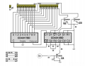
I agree with AK that the circuit in post #10, using the CD4015 shift-register would appear to be the simplest circuit using discrete logic.

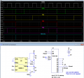
I don't have a model for the CD4015, but below is an LTspice sim using the 74HC164 shift-register.
The main functional difference is, the 74HC164 has a negative reset polarity, so requires an inverter for the reset signal.

The outputs, of course, can control the transistor to drive the LEDs.

1781968796316.png
 
Last edited:

B-JoJo-S

Joined Jan 3, 2026
451
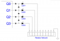
True - I had overlooked diode forward voltage drops. Should pay more attention to details. However, the intention was to show it can be done and as stated in the text, transistors would be necessary for handling the loads. The TS DID say he was planning on up to 12 LED's on a single output. Hence the need for some serious transistor power.

We also don't know what LED's the TS is thinking about. 5mm LED's with common Vf of between 2.0Vf to 3.8Vf running between 5mA to 20mA; or some other much higher current COB LED's that may run at 350mA. My - um - confusing diagram (missing dots) doesn't change with or without dots. But if you need dots and resistors:

Screenshot 2026-06-19 at 9.26.43 AM.png
Values are not listed because the TS is at liberty to use whatever voltage they desire. 5V has been stated, so assuming 3Vf for each LED and 0.6Vf for each diode - YIKES! THAT'S 2.4Vf from Q3. 5V isn't going to be enough. Of course this approach is going to take more engineering than I feel like doing. I'm trying to help with the problem, not solve it.

edit: I mis-drew my R-Network. Should be 11 pins, not 10.
 
Last edited:

B-JoJo-S

Joined Jan 3, 2026
451
The problem with the approach, as shown (and I'm assuming that you have current limiting resistors to the right of each LED is that the voltage drop across the diodes changes as different pins dominate. For instance, when Q1 is driving LED1, you have only one diode drop, but when Q3 is driving it, you have four diode drops. That's an additional 2+ V that is not being dropped across the current limiting resistor, which will reduce the LED current. Depending on the voltage that the system is running at, that could have a significant impact on the LED current.

If you use switching transistors, you still need current limiting resistors in the bases, so you would have seven diodes and four resistors (eleven components) in your switching logic before the transistors. Using the approach I recommended in the first response, you need ten resistors and four diodes (to suppress voltage-divider interaction between the output. Using bussed resistor arrays, you would only need eight components (four diodes, three bussed SIP arrays and a single resistor), making the interconnect extremely easy.

View attachment 368520
Another alternative, since switching transistors already need to be used, is to use them to also implement the wired-OR logic directly at the LEDs.

View attachment 368521

This requires more transistors, but is simpler overall, especially if not using resistor arrays in the prior approach.
I have to agree, I like the first approach, using a single 11 pin R-Network. Far fewer transistors and one R-Net. makes the whole thing a lot more compact. And the TS can use a higher voltage to accommodate use of 12 LED's. But they'd have to be Series / Parallel sets of LED's. Much like those LED strings you tape up to your project. THOSE come with their own current limiting, so aside from biasing the transistors (or use of MOSFETs) this project is highly doable. In my opinion.
 

B-JoJo-S

Joined Jan 3, 2026
451
I don't know if anyone realizes it but if you reset on Q4 then LED1 is going to appear to be on all the time. Depending on how quickly the TS is sweeping those four outputs it could look like one or more LED's are always lit.
 

gaber2611

Joined Mar 14, 2013
329
Been looking for a schematic of a led chaser circuit. I only need the first 4 outputs of a 4017 IC but I want outputs to stack on. 1 on, 1&2 on, 1,2 &3 on,1 2 3 & 4 on then all off. Then atart again.
5 volts powered. Loads are 4 2n2222 transistors each running a dozen or so LEDs.
I can make the. Chaser with a 555 timer but I have tried many signal diode combinations that don’t give me the. Pattern.
please help
please, any help is appreciated
What time between each output and the second?, Second for example?
 

ThePanMan

Joined Mar 13, 2020
938
@ThePanMan What voltage did your cousin use to run the counter and flipflop?
I don't know. I'm assuming 5V since Q1's base is connected to a 5V source. It would also make sense that assuming a 2.5Vf (LED) and a 0.6Vf drop through Q2 or Q3 plus 220Ω would suggest (5V-3.1Vf) ÷ 220Ω would be 8.6mA through the LED. At 12V that would be (12V-3.1Vf) ÷ 220Ω = 40.5mA. That's going to burn out those LEDs.
 
Top