(Logisim)Incrementing with only 2-Input-NAND-Gates

Thread Starter

RavenRad

Joined Apr 4, 2017
2
Hello everyone.So,I have been doing a project for some time now,and I have been stuck on a part,which I can't really figure out.So,my problem is next,I am working on a project in Logisim and have been assigned to edit some things on a circuit out.
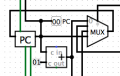
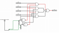
The task is the following: From the program-counter(image is down below), I have to increment using only 2-Input-NAND-Gates,which where the Multiplexer is on the logiclevel.And the Multiplexer and the Decoder in the bus(including the Adresscoding) are also on the logiclevel.So,does anyone have an Idea on how to start here? Any help would be appreciated,thank you.
 

Attachments

WBahn

Joined Mar 31, 2012
30,045
What is a "circuit out" that you have to edit thing on? What do you mean by "which where the Multiplexer is on the logiclevel"? What is the "logiclevel" and what relevance to the problem does it have?

You can implement ANY Boolean logic function using nothing but 2-input NAND gates.

Are you supposed to take the signals from the right hand bus and create a logic circuit that produces a signal to feed into the left hand bus that is one greater than the value on the right hand bus?
 

Thread Starter

RavenRad

Joined Apr 4, 2017
2
What is a "circuit out" that you have to edit thing on? What do you mean by "which where the Multiplexer is on the logiclevel"? What is the "logiclevel" and what relevance to the problem does it have?

You can implement ANY Boolean logic function using nothing but 2-input NAND gates.

Are you supposed to take the signals from the right hand bus and create a logic circuit that produces a signal to feed into the left hand bus that is one greater than the value on the right hand bus?
The "out" was from edit things out on the circuit.My bad grammar :D . Logic level are the truth tables(project->analyse circuits).

I am supposed to increment the signals from the left side using NAND gates,which can only accept 2 inputs.
 

WBahn

Joined Mar 31, 2012
30,045
Where does the output of your incrementer go?

Be that as it may, look at how addition of 1 to a binary number works and focus on the logic for a given bit position.
 

MB Design

Joined Apr 20, 2017
6
First, to make things clear, we have to do modifications on the hardware-model of a CPU. To be more precise, components which are typical parts of the register-transfer-layer (RTL) have to be substituted with parts of the logic layer. E.g. substitution of a 2to1 multiplexor (with is part of a RTL) with 2 and-gates and 1 or-gate (which is part of the LL).

The screenshot obove shows only the inner of the Program Counter (PC) itself. But there are also an adder and a multiplexor (4 to 1) beside the PC which are also parts of the PC. So the task is to substitute this multiplexor with logic gates and to substitute this adder with 2-input-nand gates.

I already subtituted the multiplexor (4 to 1) with 4 and-gates and 1 or-gate (I know that it is also possible to build an equivalent circuit only with 7 nand-gates but the first one uses less components and less space so I decided to take this one).

So, I`m still trying to substitute the adder beside the PC. The adder seems to be a standard-adder of logisim (screenshot in attachment) with the constant 1. I tried to do this but I think there will be approximately 30 2-input-nand gates. So my question is, if there is a way to build such a circuit in a smaller way.

Thanks in advance.
 

Attachments

WBahn

Joined Mar 31, 2012
30,045
Assuming the functionality is the same, why do you say that 4 AND gates and an OR gate take up less space than 7 NAND gates? If we are talking CMOS (which is probably the case) and if all of these gates are two-input (which I don't see how they could be), then the former requires 30 transistors while the latter requires 28.

But how are you implementing a 4-to-1 MUX with just 4 AND gates and 1 OR gate. I'm assuming that the OR gate is a 4-input OR gate and that you have a 2-input AND gate for each data input with the output of each going to the OR gate? If so, then how are you decoding the two select bits? Even if you are using 3-input AND gates, you would still need two inverters.

Be careful about assuming that circuit size is determined by the number of logic symbols in the schematic -- these are only loosely correlated.

As for the adder, look at the logic for adding two arbitrary values and then see what logic can be trimmed if one of them is always a fixed value. It can be simplified significantly in the case of the constant being a 1.
 

MB Design

Joined Apr 20, 2017
6
I`ve forgotten to mention that I use the 4-to1 MUX with 4 and-gates and 1 or-gate ... and two inverters.
But the 2 selectors still make problems because now I have 4 wires (which are the 2 x selectors and 2 x their inverting).
But as you can see in my screenshot above there`s just one wire from the selector-input which leads to the controller. So I have to manage these 4 wires which should be eventually one wire in the controller.

Thanks for your advice regarding the circuit size!

Regarding the adder: The logic which comes into my mind is a "8-bit-full adder"
The disadvantage is, that it will become extremely large and I do not know if there would be a better solution (in case of the constant 1)
 

WBahn

Joined Mar 31, 2012
30,045
Okay, so correct me if I'm wrong -- your 4:1 MUX consists of four 3-input AND gates, one 4-input OR gate, and two inverters. If so, that would be 46 transistors and you would have four gate delays from each data input to the output (and five for the select lines to the output). Using four 3-input NAND gates, one 4-input NAND gate, and two inverters you could use 38 transistors and have two gate delays for data and three for selects.

Are you sure that the single wire from the select lines to the controller isn't a 2-bit wide bus? The only way to get two bits of data over one wire is to time-division multiplex them and I can pretty much guarantee that this isn't the case here. The inversions should take place within the MUX.

Take the circuit for an 8-bit full adder and see what happens when you force one of the inputs to be the constant 1.

You should also be able to come up with the same highly simplified circuit by just looking at what has to happen to each bit when you add 1 to an arbitrary binary number.
 

MB Design

Joined Apr 20, 2017
6
yes. you`re right. I just have connected the wires from the controller (2-bit bus) with the 4 to 1 multiplexor. (screenshot in the attachment) But there is still a problem with the connection (bit values). I took the version with the NAND-gates.
 

Attachments

Top