Facebook
 Google
 GitHub
 Linkedin
I'm going to build a device to actuate a solenoid valve when the water level in a tank reaches a set low mark, and then shut off the valve when the tank has filled to a set high mark. I'd like to use hall effect sensors with a magnet in a small bouyant plastic float on the inside of the tank.
I've come up with this logical diagram. When the water level reaches the low level, the signal into the OR gate will activate the solenoid. At the same time, this will activate the AND gate (because the high sensor has an inverter), with this signal feeding into the OR gate as well. This will latch the activation signal until something happens to turn off the AND gate- which will happen when the high sensor detects the magnet. Here's the logical view I came up with:
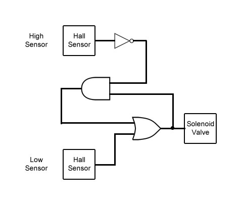
Since this uses exactly one inverter, one AND and one OR gate it would be kind of wastefull to use 3 discrete ICs to implement this. So I thought I'd implement the gates with NPN transistors instead. Also, it just seemed kind of interesting to do.
Now, if at any point you begin to think I may not know what I'm talking about, you're most likely correct haha. I'm a software guy but I like tinkering with hardware. But its been many years and I'm a bit rusty even on what I was able to teach myself back then. But thats not going to stop me!
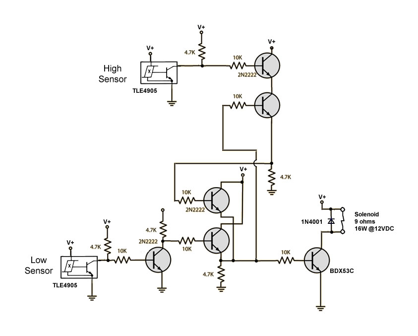
Anyway, after some research I came up with this implementation. Would love to get critiques before I go breadboard it. In a few circuits I found out there, the designer used diodes between transistor outputs/inputs to protect the transistors, but I don't quite understand why those would be needed or exactly where. So if it looks like voltage swings would damage the transistors and I need diodes to protect that, I'd be interested in learning where. One small change from the logical diagram is that the hall sensor I found has an open collector and from what I gathered reading the spec pulls the output to ground in the presence of magnetic induction. So for this sensor, its actuall the bottom that needs to be inverted. I also added a BDX53C transistor to drive the solenoid.
Forgot to put this on the diagram, but V+ is 12VDC, from a wall wart.
Any chance this will work? How far off am I?
Cheers,
Eric
I've come up with this logical diagram. When the water level reaches the low level, the signal into the OR gate will activate the solenoid. At the same time, this will activate the AND gate (because the high sensor has an inverter), with this signal feeding into the OR gate as well. This will latch the activation signal until something happens to turn off the AND gate- which will happen when the high sensor detects the magnet. Here's the logical view I came up with:
Since this uses exactly one inverter, one AND and one OR gate it would be kind of wastefull to use 3 discrete ICs to implement this. So I thought I'd implement the gates with NPN transistors instead. Also, it just seemed kind of interesting to do.
Now, if at any point you begin to think I may not know what I'm talking about, you're most likely correct haha. I'm a software guy but I like tinkering with hardware. But its been many years and I'm a bit rusty even on what I was able to teach myself back then. But thats not going to stop me!
Anyway, after some research I came up with this implementation. Would love to get critiques before I go breadboard it. In a few circuits I found out there, the designer used diodes between transistor outputs/inputs to protect the transistors, but I don't quite understand why those would be needed or exactly where. So if it looks like voltage swings would damage the transistors and I need diodes to protect that, I'd be interested in learning where. One small change from the logical diagram is that the hall sensor I found has an open collector and from what I gathered reading the spec pulls the output to ground in the presence of magnetic induction. So for this sensor, its actuall the bottom that needs to be inverted. I also added a BDX53C transistor to drive the solenoid.
Forgot to put this on the diagram, but V+ is 12VDC, from a wall wart.
Any chance this will work? How far off am I?
Cheers,
Eric