
 Facebook
 Google
 GitHub
 Linkedin

I purchased a Zeroplus Logic Analyzer and I think I made a mistake. It gets very good reviews but the documentation is horrendous! There seems to be no tutorial or support forum that I can find.
I basically bought the thing as a toy and a learning experience.
Basically I know very little about logic analyzers.
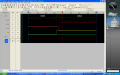
If no one here has a Logic Cube, maybe these things are generic enough to provide some help. I have included a screen shot of my screen.
What I am trying to do is to analyze the data sent to an LCD screen. I am sending the letter Z over and over to the LCD in 4 byte mode, so I should be seeing a 0x5 and 0xA.
I grouped my 4 data bits into a bus and trigger off the enable pin of the LCD. I am using the analyzer for a clock and it is set to 1MHZ. My PIC is running at 250khz.
I am indeed seeing the 0x6 and 0xA but I am also seeing a bunch of other data. If you look at the screen shot, there are several transitions after the 0xA. They are 0xD, 0x9 and 0xB. I have circled these in the attached picture.
I have tried triggering on a high enable, going high and going low. All seem to have similar results.
Also I ungrouped the bus into channels and it looks like data is being captured when enable is low. Now I know data does start to be captured until enable goes high but I thought that no data would be captured unless the trigger was high.
When I run repetitive, very little data seems to be captured. Why is this?
Also in repetitive run, I can see my enable going high and when it does, the appropriate data lines are high but I still get a lot of garbage data that shoes up when enable is low.
I basically bought the thing as a toy and a learning experience.
Basically I know very little about logic analyzers.
If no one here has a Logic Cube, maybe these things are generic enough to provide some help. I have included a screen shot of my screen.
What I am trying to do is to analyze the data sent to an LCD screen. I am sending the letter Z over and over to the LCD in 4 byte mode, so I should be seeing a 0x5 and 0xA.
I grouped my 4 data bits into a bus and trigger off the enable pin of the LCD. I am using the analyzer for a clock and it is set to 1MHZ. My PIC is running at 250khz.
I am indeed seeing the 0x6 and 0xA but I am also seeing a bunch of other data. If you look at the screen shot, there are several transitions after the 0xA. They are 0xD, 0x9 and 0xB. I have circled these in the attached picture.
I have tried triggering on a high enable, going high and going low. All seem to have similar results.
Also I ungrouped the bus into channels and it looks like data is being captured when enable is low. Now I know data does start to be captured until enable goes high but I thought that no data would be captured unless the trigger was high.
When I run repetitive, very little data seems to be captured. Why is this?
Also in repetitive run, I can see my enable going high and when it does, the appropriate data lines are high but I still get a lot of garbage data that shoes up when enable is low.
Attachments
-
 167.9 KB Views: 53






