Its a loadcell / strain gauge : https://www.robotgear.com.au/Product.aspx/Details/1728-Load-Sensor-50kg
I got the original diagram online to turn the 3 wire output into a 4 wire output required for my INA122 amplifier.
I currently have it all wired up with a 4 wire loadcell and this new loadcell is a straight replacement for it.
That PDF you linked means nothing to me
hi,
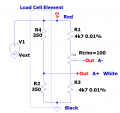
Checked your link, its a 'half bridge'.
So as you say you need two resistors adding across the Vext wires Red and Black.
The junction of the two resistors is connect to A-.,, the White wire to A+.
Its important that the two resistor are exactly the same value, otherwise you get a large offset reading on the Scale.
The usual way to get around this is to have two identical resistors connected to the ends of say a 100 ohm trim pot.
The wiper of the trim post is connected to A-.
So when there is no weight on the scale the trim pot is adjusted to give a zero weight reading on the scale.
I just need to know if both of those diagrams are the same - I have no knowledge of electronics and just going to copy the bottom one (which is correct for my application) but would be easier for me if I can do it the same as the top one.
thanks again
 Facebook
 Google
 GitHub
 Linkedin

")