Facebook
 Google
 GitHub
 Linkedin
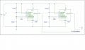
Hey everyone, I am currently working on an LED display project for a friend. The basic circuitry is such that, there are four banks of 10 (40 in total) super bright white LEDs that pulse on and off in a 40 second period. So bank one on for 0-10s, bank two on for 10-20s and so on. How I am controlling this is with two LM555 timers that oscillate in the astable mode, one with a 20 second period (off 10 on 10), the other with a 40 second period (off 20 on 20). To generate the 50% duty cycle, I used the 50% cycle equations and schematic that can be found on all of the LM555 data sheets. I did NOT use the standard LM555 astable setup. See page 10 on this PDF for the setup I used http://www.national.com/ds/LM/LM555.pdf. I then run these signals through the appropriate NAND gates to light up each bank of LEDs separately. My digital logic is very simple, just four states, 00, 01, 10, 11, one for each bank.
I understand how to set up my timers and do the logic, and have all that working, but here is my question. For whatever reason, both of the timers when I first turn the circuit on, do not oscillate correctly initially. Instead of following their defined periods, they both stay on longer than they should. After that initial strange period, both give output exactly as I would expect them to, correct periods for each. I am wondering if the LM555s have some sort of initial charge time for the timing capacitor when you first turn them on. My problem is that, the two timers have slightly different initial delays, meaning that my waveforms that drive my logic are out of sync by about 2 seconds. Obviously this is going to change the functionality of my LEDs, and is something that I need to overcome. I don't have my schematic on my computer yet (did it by hand first) but I will try and get it up. Just so you know, I am currently using 1000uF electrolytic caps on both 555s. If you want more details I can give them, but at the moment I just want to see if anyone has any ideas about how to get around this problem, I really think it has something to do with the large timing caps. I could try using a smaller cap and larger resistors, but I don't want to cut down too much voltage for the output signal, that is why I started with 1000uF. Any speculation you can give would be great. Thanks.
I understand how to set up my timers and do the logic, and have all that working, but here is my question. For whatever reason, both of the timers when I first turn the circuit on, do not oscillate correctly initially. Instead of following their defined periods, they both stay on longer than they should. After that initial strange period, both give output exactly as I would expect them to, correct periods for each. I am wondering if the LM555s have some sort of initial charge time for the timing capacitor when you first turn them on. My problem is that, the two timers have slightly different initial delays, meaning that my waveforms that drive my logic are out of sync by about 2 seconds. Obviously this is going to change the functionality of my LEDs, and is something that I need to overcome. I don't have my schematic on my computer yet (did it by hand first) but I will try and get it up. Just so you know, I am currently using 1000uF electrolytic caps on both 555s. If you want more details I can give them, but at the moment I just want to see if anyone has any ideas about how to get around this problem, I really think it has something to do with the large timing caps. I could try using a smaller cap and larger resistors, but I don't want to cut down too much voltage for the output signal, that is why I started with 1000uF. Any speculation you can give would be great. Thanks.