LM3886 In parallel - overheating issues - Behringer Truth B2031

sghioto

Joined Dec 31, 2017
8,634
Just an update regarding the overheating issue, as a last resort I decided to try higher value ballast resistors. I replaced the 0.1ohm with 0.75ohm 3W. Lo & behold the amp is not overheating anymore. It's still getting warmer than the other speaker, but there is a massive difference. It's no longer going into protect & making the "ticking" noise it was before. Playing it side by side with the other, I cannot tell a difference in volume at all either. So my question now is, am I doing any harm by increasing the value of the resistors?
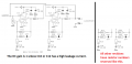
You lose a bit more voltage across the resistors is all.
 

Thread Starter

acme

Joined Jan 3, 2018
21
I went back and looked at the original circuit. There are two resistors, R17 and R20, that must be matched, both shown as 20K ohms. These two set the exact gain, and thus DC offset, of the two modules. In the parallel amplifier circuit posted farther in, the resistors for setting gain on the two devices are shown as 0.1% tolerance, which is not common to find in most audio equipment, and certainly costs a lot more. So, given that you did see quite different voltages, it might be worth the effort to measure those two resistors actual values. That might be the source of the problem.
Thanks so much for that. That is what I've been trying to figure out, "what sets / how to adjust the offset". Those were actually the first resistors I checked (not even knowing they adjust the offset). They were absolutely identical, but..... here's a question: If the actual amp ic's are not identical (surely there must be differences between each batch), then what is the point of using identical resistors? Perhaps I can play with those values & try get the offset closer?
 

MisterBill2

Joined Jan 23, 2018
27,611
Thanks so much for that. That is what I've been trying to figure out, "what sets / how to adjust the offset". Those were actually the first resistors I checked (not even knowing they adjust the offset). They were absolutely identical, but..... here's a question: If the actual amp ic's are not identical (surely there must be differences between each batch), then what is the point of using identical resistors? Perhaps I can play with those values & try get the offset closer?
OK, those are the resistors that affect the gain and hence the offset. If they are identical then there is something else having an effect. That could be a capacitor with a small amount of leakage, or even some surface contamination on the board surface. It might even be a sight imbalance of the dual supply voltages, ( I don't recall if the modules use both positive and negative supplies.) So a safe effort would be verifying that the boards are clean in that channel area, and verifying that the supply voltages match at the device. Also examining the solder connections for slightly weak joints. Checking for some sight capacitor leakage current is much more complex, but inspecting capacitors for any bulges on top is not hard.
 

Audioguru again

Joined Oct 21, 2019
6,826
I went back and looked at the original circuit. There are two resistors, R17 and R20, that must be matched, both shown as 20K ohms. These two set the exact gain, and thus DC offset, of the two modules.
No.
R17 and R20 set the AC gain. C10 and C12 cause the DC gain to be exactly 1 regardless of the values of R17 and R20.
A difference in the values of R17 and R20 causes a small amount of heating in the power amp ICs only at the high peak levels of the signal.

Do not look at Revision B where R18 and R18, R20 and R21 are probably swapped.

If your speaker drivers are 4 ohms then bridging the amplifiers will probably overload the amplifiers and power supply at high output levels. They paralleled the amplifiers to be able to have enough output current to drive 4 ohms.
 

MisterBill2

Joined Jan 23, 2018
27,611
Either AG is looking at different drawings or has a different equation for amplifier gain. I do see that there are capacitors in series in the driver circuit on the other sheet. But there is a resistor to common for both positive inputs, and as there is no other connection to the inputs that must therefore be Rin, and the single 20K resistor must be the DC feedback, so that the DC gain is still Rf/Rin. And so while the calculated gains are similar the actual DC conditions are also affected by leakage in any of those severa capacitors in the circuit. And unfortunately not all capacitors have zero leakage. AND, given that the overheating stayed when the IC was replaced, the fault seems to be in some other location.
 

SOQ

Joined Feb 1, 2023
4
Thanks so much for that. That is what I've been trying to figure out, "what sets / how to adjust the offset". Those were actually the first resistors I checked (not even knowing they adjust the offset). They were absolutely identical, but..... here's a question: If the actual amp ic's are not identical (surely there must be differences between each batch), then what is the point of using identical resistors? Perhaps I can play with those values & try get the offset closer?
Hello
I have exactly the same issue with B2031 in one speaker. Did you get any further other than increasing the two Rout from 0.1 to 0.75 Ohm?
I have a theory (mentioned in this thread) on aging capacitors as the problem appeared after many years of use!
 

MisterBill2

Joined Jan 23, 2018
27,611
I have seen other amplifiers shown in manufacturer's application notes and NONE OF THEM use power amplifiers in parallel without a scheme to servo the DC outputs to match. I would NEVER put power modules solidly in parallel as in these amplifiers. Given that they are driving only speakers internal to the "monitor box", a bridge driver circuit could do the job as well.

If measuring the individual outputs shows a voltage difference the logical culprits would be C10 and C12, the 10 Mfd 50 volt capacitors providing the common connection for the inverting input of the two output modules. They would both be replaced by LOW LEAKAGE capacitors of the same value but a higher working voltage.

And I really wonder what the original designer of that output circuit was thinking to do it that way. It would be interesting indeed to hear that explanation.
 

SOQ

Joined Feb 1, 2023
4
I have seen other amplifiers shown in manufacturer's application notes and NONE OF THEM use power amplifiers in parallel without a scheme to servo the DC outputs to match. I would NEVER put power modules solidly in parallel as in these amplifiers. Given that they are driving only speakers internal to the "monitor box", a bridge driver circuit could do the job as well.

If measuring the individual outputs shows a voltage difference the logical culprits would be C10 and C12, the 10 Mfd 50 volt capacitors providing the common connection for the inverting input of the two output modules. They would both be replaced by LOW LEAKAGE capacitors of the same value but a higher working voltage.

And I really wonder what the original designer of that output circuit was thinking to do it that way. It would be interesting indeed to hear that explanation.
Thank you for fast response in this old thread.
I agree, It ought not be a good design. I am now trying to find what is wrong. It seems like overheating happens under load ( 30 min of rather loud music the other day).
Yesterday I had the monitor on with no input for 3h measuring 3 voltages at IC Outs and Loudspeaker out to determine what´s going on. No overheating or excessive currents from one IC to the other and 3mV DC offset to loudspeaker. I also heated the whole amp with a hairdryer with no reaction other than 3 mV ICout rise in one of the IC´s. Turning the dryer off the amp went back to normal temperatures. I will test it further.
 

MisterBill2

Joined Jan 23, 2018
27,611
If changing that series resistor from 0.1 ohm to 0.75 ohms greatly reduced the heating, then increasing the resistance of both to 1 ohm might reduce the heating problem to a level that can be ignored.
It might also possibly be worthwhile to contact the manufacturer to see if they offer any solutions, since it may be that this has happened to other users as well. Some organizations take quality beyond sales rather seriously.
 

SOQ

Joined Feb 1, 2023
4
Now having examined the amplifier more I have not found any oscillation problems. Putting it back together I discovered I could not get one of the 3886 in good contact with the heatsink. The PCB had not been correctly cut - it had a rim preventing the IC to get all way in. After correcting that I tried again but the amp still got into protection ("Spike") mode too early. The driver is 4 Ohm and with 100Hz it started to cut down at 11 V (RMS) AC. Tried with lower DC Voltage feed which seemed to be the right thing. Originally it is powered by a 150VA 2*27,8 V toroid that gives 2x40V DC and that is to much according to almost all recommendations - especially for 4 Ohm drivers. Swapped it for a 2x22V 120VA transformer. With this one I can get 19,5 V (RMS) AC of 100Hz without protection activating! That was with max input from the CD-player and at that point DC Voltages was some +/- 29 volt so it probably is almost clipping.
My conclusion is that one or two of the bass driver 3886 IC´s in the faulty speaker (the other one works good) has been damaged by heat earlier, probably due to bad quality control at assembly line! Lowering voltage seems to have made the amps not go to protection mode.
 

NetkoDrugi

Joined May 24, 2023
4
Hello, I'm new on this forum and i had the same overheating issue on both of my speaker amplifiers.
This thread helps a lot identifying problems.
My speakers had overheating issue due to oscilations caused by failed C3 and C6, 6800uF 50V capacitors.
A year ago I replaced: C3 and C6 With ELNA Lao, IC4 and IC5 with ST LM7815CV and LM7915CV added heat-sinks on them.
They were working just perfect until this afternoon when one failed with pop sound and the bass driver went forward about 1CM and limit LED on.
I'm measuring 7VDC on woofer output, The LM3886T amplifiers are all fine, got them tested. I can't find what is causing the limit protection...
Someone to help?
 

SOQ

Joined Feb 1, 2023
4
The LM´s are supplying +/- 15 V Dc to a lot of dual OP-amps (4580´s) that makes all of the filtering before passing signals to the 3886´s. Some of he 4580 OP-amps might have been destroyed. Replace the regulators, check output from them (+/- 15 V Dc) , check output from OP-amps at no signal in - it should be close to 0 V AC & DC.
Sten
 

NetkoDrugi

Joined May 24, 2023
4
The LM´s are supplying +/- 15 V Dc to a lot of dual OP-amps (4580´s) that makes all of the filtering before passing signals to the 3886´s. Some of he 4580 OP-amps might have been destroyed. Replace the regulators, check output from them (+/- 15 V Dc) , check output from OP-amps at no signal in - it should be close to 0 V AC & DC.
Sten
Thank you Sten, this explanation is very clear.
To clarify, a year ago when I replaced the above parts, the main problem was 7915, which has -27V on it's output.
That possibly damaged the OP amplifiers, but not so severe to total failure, time did...
Also it's good to know that the speakers were turned off for few hours only once in their lifetime and I'm not using "auto power on" function.

Now, the outputs of both negative and positive regulators are just fine, I have reading of +15,02 VDC and -14,98 VDC, anyway I'm going to check all the OP amplifiers later
 

MisterBill2

Joined Jan 23, 2018
27,611
If it is possible, adding some Zener diodes to clamp the 15 volt supplies at 16 0r 17 volts should reduce the chance of such failures repeating. And during correct operation the Zener clamp circuit should have no effect.
 
Hi, I don't know if you ever got to the bottom of your issue but I thought this might be worth knowing for anyone with Truth 2031s that are reading this. I have had a pair of these for many years but they have not been in service for about 5 years. Yesterday I got them out to test before trying to sell them. I found that one would not switch on - no green LED. +15v and -15v seemed OK. I ended up removing the pcb and trying to trace the mute circuit. The only available schematic is not correct to this pcb and IC11 is actually IC8 - the mute op-amp. I then noticed that some of the electrolytic caps including the big 6800uF plus a 4-lead opto coupler had been 'stuck down' for vibration purposes with the dreaded Japanese, and now Chinese, brown glue. This was used in Japan in the 80s and early 90s before it became known that it ages and becomes conductive, and also corrodes the copper track and component leads. It has reputedly made a reappearance in pcbs from China recently. I had not caught this in time but the pcb in the other speaker was the same but had not really started to cause an issue. The main damage was to fine tracks and vias around the opto-coupler. I have not repaired them yet and it will be a VERY difficult task. A steady hand and fine wire, plus I intend to drill a hole adjacent to pass the repair wires through from one side to another. This is worth checking on any 2031s. The best way to deal with it is to remove the components and clean off the glue with a knife and glass fibre brush etc. This will also reveal where the glue has eaten under the solder resist. If you are not too familiar with removing components from double-sided boards then ask someone who is or it is easy to wreck the board.
The attached pics don't show the areas cleaned up but are as found, with the glue scraped off. I will take some better pics of the other 'good' pcb in case anyone has a really bad board and wants to know where the traces go to/from.
I first encountered this awful glue on an ignition unit for a Kawasaki V-twin mower engine. It had eaten not only the track but component leads too, and had resulted in ignition timing chaos for the second cylinder which had burned out an exhaust valve.
 

Attachments

I also had an issue many years ago with a voltage regulator dying. The LM7815 and 7915 in the amps are not happy and were getting very hot. If I recall correctly they have a rated max supply voltage of 37 volts. These are fed from 41 volts with a series dropper resistor, which is a terrible design. It would have been better to have a separate 15 - 0 - 15 winding on the toroid. Anyway, I attached a heat sink to each one and it seemed much better after that.
 
Top