 Facebook
 Google
 GitHub
 Linkedin
Audioguru again
- Joined Oct 21, 2019
- 6,826
The schematic you posted does not show the power amplifier section that has the problem.
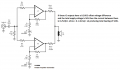
The difference in DC voltage at the outputs of the paralleled ICs produces a current in their series output resistors that heats both of them. The amplifier manufacturer probably selected matched ones so the voltage difference and resulting current and heat are tiny.
Here is a schematic from the datasheet with my comments:
Attachments
-
 84.2 KB Views: 36


