hi data,
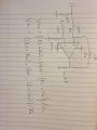
This is what LTSpice shows.
The 1n charges up.
E
EDIT:
For the 100k to 0V, I simply chose a high value, so it would not load the 1nF input signal, but at the same time provide a DC current path to 0V for the Non Inv input.
The 1meg is add a little positive feedback in order to speed up the rising edge of the signal.
BTW: I guess you know the Vout signal will be a 'squared' up version of the 0.04V 40kHz signal.??
So using the 100k to 0v and 1 meg feedback resistor how do I calculate Vth and Vtl? This is what's confusing me cause the circuit works I just cant calculate these values
hi,
When using an open collector Comparator, the values for the Rhys can be easily calculated using the PDF equations.
A problem arises when the Comp is a standard OPA, which has an active Output stage.
The tests I have run on your circuit show that the 1meg has a VERY small effect on the hysteresis, in my opinion I would not concern yourself on the hysteresis.
Can you post a sketch showing what you expect the Vout signal to be.?
I assume you are trying to amplify a 40kHz signal echo period pulse, what is the time length of the expected echo pulse.?
E
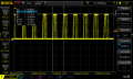
This is my output when connected to an oscilloscope, I sadly don't have one available at the moment. My circuit works its just I wanted to calculate the hysteresis.
When I connected my circuit like shown below It works. Can I use the circuit shown and the formula to calculate hysteresis? I just want to be able to use the correct formula
Looks like it needs some hysteresis, or you have some pickup or power supply
issues.
Start with power supply, what are you using on OpAmp pins to bypass the power pins ?
Preferred is tanatalum or polymer tantalum (better) in parallel with a .01 uF ceramic disk.
Both power pins bypassed this way.
Single point ground as best as possible.
Pickup, obviously long leads potetial issue. Also 60 Hz line pickup since you have HiZ nodes
in circuit subject to pickup. If you have flourescent lights in lab turn them off. Even Monitors,
old or new style, potential noise generators. On equipment like that noise filters on their
power cord good idea.
I think this will work.
I biased the input to the buffer and comparator at 2.5v.
I reduced the gain on the gain stage to about 10 to reduce the buffer output and avoid clipping. So at .04v input, output will be about 400mv peak. If added to the bias voltage, the output+bias sums to 2.9 (100mv below 3v).
I then set the comparator reference to 2.8v (0.3 volts relative to the bias voltage but you can set it as you wish). Hysteresis with the values shown is about 5mv. Note however that there is no input headroom and any increase of the gain stage input voltage may cause clipping of the gain stage output. You can reduce the gain further if needed. I've also added bypass caps (c5,6) and filter a cap (C7) at the Ref pin.
See below,
 Facebook
 Google
 GitHub
 Linkedin