You have two R1's in the schematic.
But it requires two resistors to provide a voltage divider to generate the hysteresis voltage.
One resistor does not form a divider.
You have two R1's in the schematic.
But it requires two resistors to provide a voltage divider to generate the hysteresis voltage.
One resistor does not form a divider.
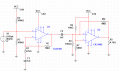
For the comparator, I have the voltage divider set by R6 and R7. I have the feedback resistor Rf2 providing the hysteresis feedback to the comparator. My question is, is it enough having just Rf2 there or do I need another resistor connect in series to the non-inverting input of the comparator?
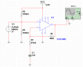
I have built a CA3140E non-inverting amplifier circuit and it works on the breadboard fine. My problem is simulation in Multisim NI 14 is giving me a very strange output. The amplifier is on a single supply on 5 V but Multisim NI 14 is giving me an output of 8 V? This is clearer not right. I have attached my simulation circuit, any help at all would be greatly appreciated. Ive also attached my oscilloscope output from comparator and amplifier along with the full circuit.
hi,
What is the output resistance of the V1 voltage source.?
If it zero, then the 100k/100k divider junction is grounded, I did point this out some posts ago, use a coupling capacitor.
E
Update:
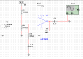
Ive made an error on the input voltage, this should be 0.04 V. Having corrected this the amplifier simulation works as expected with the gain set. My problem now is that it will not run with the comparator circuit. I have no idea why? There is no output signal from the comparator although it works on the breadboard.
hi data,
I keep trying to explain that R2 and R3 form a potential divider, so pin #3 should be at +2.5V, but when you connect the V1 source signal you are grounding pin #3.
Add a 1nF of 10nF capacitor between V1 and the divider. 0.04V input.
hi,
The circuit layout looks correct, it is a little messy.
The Yellow trace is similar to the LTSpice sim plots, so it could be your Multisim circuit..
Post the Multisim circuit diagram.
E
hi,
The circuit layout looks correct, it is a little messy.
The Yellow trace is similar to the LTSpice sim plots, so it could be your Multisim circuit..
Post the Multisim circuit diagram.
E
Haha it is indeed. I have a feeling it is the multisim model for the ca3140e, I would of liked to have it working but as its working on my breadboard I can live with that. Now to work out the hysteresis calculation
I have a question with regards to the comparator. In my circuit the 100k R4 resistor serves the purpose of providing a DC path to ground at the input of the op-amp. Using the analog website https://www.analog.com/en/analog-di...g-comparator-instability-with-hysteresis.html it says hysteresis is set by R3 and R4. So in the case of my circuit I know Rf2 is taken as R4 but do I take my 100 k R4 restore as R3? Im getting confused as R3 is in series in the analog.com example but my R4 is connected to ground to provide the DC path.. Do I include this in my calculation?
Okay so I don't have an oscillscope sadly. The output of my comparator is connected to an arduino pin, the program senses if the pins high or low. The comparator should be high when an object is detected by my ultrasonic sensor, the program WORKS with my original schematic the problem was I didnt know how to do the mathematics to calculate the hystersis.
It does not work with the 100k resistor in series as the output is always high (even when no object detected).
It does work with the 100k in series and another 100k resistor before it connected to ground.
 Facebook
 Google
 GitHub
 Linkedin