Facebook
 Google
 GitHub
 Linkedin
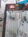
hi Data,Hi Eric, could you tell me the function R2 R8 and R9 preform?
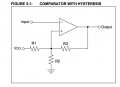
As you may know a OPA input needs a DC path to ground on its input pins in order to work, R2 provides that path.
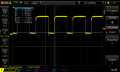
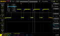
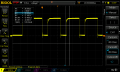
For most Comp's some external positive feedback [hysteresis] from Vout to the NI pin is required to give a fast turn On/Off of the Comp and it reduces the possibility of Vout oscillation at the switching threshold, ie: R9.
As you are using a single supply, R8 helps improve the low level of Vout, by lightly loading the output pin, pulling it closer to 0V.
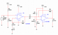
Also C4 on the input blocks the DC path of the R3, R4 voltage divider voltage from 40kHz transducer input.
E