LM317T values differ

Thread Starter

weishan13

Joined May 12, 2020
12
Hi all, i am new to electronics and i am doing this as a project.
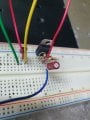
I am using LM317T voltage regulator to regulate a voltage source of Vin = 5.47V and the output Vout = 5V. Refer to attached below.
Base on the calculation, i can get Vout to be 5V. But when i connect up the circuit, my Vout becomes 3.92V, Vadj = 2.92V.
As i read online, if Vadj is connected to ground, the reference voltage will be 1.25V.

Please advise as i am not sure if my understanding is wrong or my calculation is wrong. Thank you.
1593051112911.png
 

Attachments

Papabravo

Joined Feb 24, 2006
21,225
You do not have enough headroom. There is a minimum dropout voltage that needs to be maintained where Vin is greater than Vout by some amount which I believe is greater than 0.47 V. Consult the datasheet for the actual required dropout voltage. Looks to me like Vin must be 3 volts greater than Vout. I 'd give it a bit extra and call it 3.5. So to get 5V out you need 8.5 V or greater.
 
Last edited:

WBahn

Joined Mar 31, 2012
30,051
You are violating the dropout voltage specifications:

https://www.onsemi.com/pub/Collateral/LM317T-D.PDF

This is the dropout voltage chart for the ON Semiconductor part:

1593053736953.png
So lets see about where you are on this chart. You have 400 Ω of load with 3.92 V, so that's basically 10 mA (that curve would likely be just barely below the 20 mA curve). Your differential is 5.47 V - 3.92 V = 1.55 V. You are probably pretty close to room temperature with no load. So you can see that you are almost exactly where you would expect to be (especially allowing that the curves are for typical parts and there is some variation between parts).

As you can see, the required difference between Vin and Vout increases with increasing load. It is also temperature dependent. You also don't want to design so that you are riding right on the line because the line is determined by when the output has fallen by 100 mV, which may or may not be acceptable for your design.

To be safe using this part, use at least a 3 V differential. If you know that you will never be more than 500 mA, you can probably push the 2 V overhead pretty close, but far better to give yourself a few hundred millivolts more.
 

Thread Starter

weishan13

Joined May 12, 2020
12
You do not have enough headroom. There is a minimum dropout voltage that needs to be maintained where Vin is greater than Vout by some amount which I believe is greater than 0.47 V. Consult the datasheet for the actual required dropout voltage. Looks to me like Vin must be 3 volts greater than Vout. I 'd geve it a bit extra and call it 3.5. So to get 5V out you need 8.5 V or greater.
Hi Papabravo, thank you, i will raise my Vin to be at least 3V or higher.
 

Thread Starter

weishan13

Joined May 12, 2020
12
You are violating the dropout voltage specifications:

https://www.onsemi.com/pub/Collateral/LM317T-D.PDF

This is the dropout voltage chart for the ON Semiconductor part:

View attachment 210669
So lets see about where you are on this chart. You have 400 Ω of load with 3.92 V, so that's basically 10 mA (that curve would likely be just barely below the 20 mA curve). Your differential is 5.47 V - 3.92 V = 1.55 V. You are probably pretty close to room temperature with no load. So you can see that you are almost exactly where you would expect to be (especially allowing that the curves are for typical parts and there is some variation between parts).

As you can see, the required difference between Vin and Vout increases with increasing load. It is also temperature dependent. You also don't want to design so that you are riding right on the line because the line is determined by when the output has fallen by 100 mV, which may or may not be acceptable for your design.

To be safe using this part, use at least a 3 V differential. If you know that you will never be more than 500 mA, you can probably push the 2 V overhead pretty close, but far better to give yourself a few hundred millivolts more.
Hi WBahn, Thanks for the clear explanation.
So i will need to increase Vin to at least 7 or 8V in order to obtain Vout to be 5V? There is no point in increasing the load?
In order to reach lets say 37 degree, my Vin and Vout differential should be at least 1.75V or i can reduce my Vout to at least 3.7V?
I Just want to make my understanding for the dropout voltage graph clearer.
 

crutschow

Joined Mar 14, 2008
34,418
I Just want to make my understanding for the dropout voltage graph clearer.
The dropout voltage is the minimum voltage needed across the regulator for it to maintain regulation at the output.
It's typically about 2.5V to 3V for the LM317, depending upon the output current.
Thus if the input voltage was 5.47V, the maximum regulated output would be about 3V.

There are low-dropout type regulators that require less voltage than the LM317, such as an LM1086 which has a 1.5V dropout.
 

Thread Starter

weishan13

Joined May 12, 2020
12
The dropout voltage is the minimum voltage needed across the regulator for it to maintain regulation at the output.
It's typically about 2.5V to 3V for the LM317, depending upon the output current.
Thus if the input voltage was 5.47V, the maximum regulated output would be about 3V.

There are low-dropout type regulators that require less voltage than the LM317, such as an LM1086 which has a 1.5V dropout.
Hi crutchow, thanks for the recommendation and advise. I will read up on LM1086 which probably will be more suitable for my project. The dropout voltage is quite big as well.
 

WBahn

Joined Mar 31, 2012
30,051
Hi WBahn, Thanks for the clear explanation.
So i will need to increase Vin to at least 7 or 8V in order to obtain Vout to be 5V? There is no point in increasing the load?
In order to reach lets say 37 degree, my Vin and Vout differential should be at least 1.75V or i can reduce my Vout to at least 3.7V?
I Just want to make my understanding for the dropout voltage graph clearer.
What do you mean by increasing the load?

You are using a regulator for a reason, right? You want a particular voltage for some application, right? What is that voltage? What is the maximum current that you need the regulator to provide at that voltage?

I don't know what you mean by "in order to reach 37 degree". The horizontal axis is the temperature of the device junctions (the silicon die inside the regulator). You don't have any direct control over it. The more power your device dissipates, the higher the temperature it will operate at. If you add heatsinking, you can lower that temperature. While you should design your system so that the maximum junction temperature is never exceeded (or even closely approached), you would very seldom try to design the system to operate with the junctions at a specific temperature (or, worse, rely on them being at that temperature). The exception would be systems where the entire point of the system is to control the temperature of those junctions or where close control of that temperature is important to the performance of the system; that is virtually never the case with respect to the junction temperature of a voltage regulator like this.

This is how you would typically use this chart:

Method A: Pick something that will work over the entire device operating range.
Step 1: Look at the chart and note that the worst case shown for any curve on the chart is about 2.75 V (either end of the I_L =1.5 A curve).
Step 2: Give a bit of margin to this, especially if you are going to be operating anywhere near 1.5 A, and use either 3 V or 3.5 V. Let's use 3 V.
Step 3: Add the dropout voltage to the desired output voltage to get the minimum input voltage, so for Vout = 5 V you would use a minimum Vin of 8 V.

Method B: Pick something that will work over the intended output operating current range.
Step 1: Determine your maximum output current. Let's say it is 400 mA.
Step 2: Pick the curve on the graph that is at or above your current (so 500 mA in this case), or interpolate a curve between the next larger and next lower curves, though in this case that is problematic, so go with the next higher.
Step 3: For the chosen curve, find the highest point on the curve. In this case it is a bit over 2 V, but if you know that the regulator will not be used in very cold environments it would be safe to call it 2 V.
Step 4: Give your self some margin, so use 2.25 V or, better, 2.5 V.
Step 5: Add the dropout voltage to the desired output voltage to get the minimum input voltage, so for Vout = 5 V you would use a minimum Vin of 7.5 V.

You could get more precise if you are really needing to push things by determining the power that your regulator will be dissipating and using that to determine the temperature that the junction will be operating at and determine the minimum dropout voltage from that. This is an iterative process and you can't ignore the fact that the curves are for typical devices and that devices vary somewhat.

Method A is used almost exclusively. If you are needing to even consider Method B, you are better off using a low dropout regulator. There are many options available. One possibility is the ROHM BA00 series of LDO adjustable regulators. that have a dropout of 0.3 V, which is in line with the 0.47 V you seem to be looking for.
 
Top