Think of what would happen to the LM317 when you put in 60 Volts and have a short on the output.
The regulator will blow in that case, as the Vin-Vout difference is more than the allowed maximum.
put your power supply to 160v and put a lm317 (or any other regulator) to it and see what happens.
Please make sure that you wear safety glasses and have fire extinguishers stand-by,
It is nuts that something like this needs to be discussed.
If a LM317 can take on 160v, do you think the app note linked earlier in the thread needs the pre-regulator?
And if you understand how that circuit works, you will know that the voltage drop over lm317 in that circuit is far lower than 160v, depending on that zener used.
Ok I have made my argument and Texas Instruments have also made my argument for me. You keep telling us I am wrong and yet we don't seem to be getting any reason why, only your own certainly that you cannot be wrong.
So if you believe I am so wrong please, by all means, make a counter point with some substance.
Think of what would happen to the LM317 when you put in 60 Volts and have a short on the output.
The regulator will blow in that case, as the Vin-Vout difference is more than the allowed maximum.
The floating-mode operation of adjustable three-terminal regulators such as the LM117 family make them ideal for high voltage operation. The regulator has no ground pin; instead, all the quiescent current (about 5 mA) flows to the output terminal. Since the regulator sees only the input-output differential, its voltage rating — 40V for the standard LM117 series and 60V for the high voltage LM117HV series — will not be exceeded for outputs of hundreds of volts.
Put a resistor in series before the pot on the adjust pin with an appropriate rating to make sure the differential isn't exceeded and boom, it works as intended.
I have one downstairs rigged for 52V max with a standard LM317. want a picture?
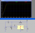
Well, here is basically how the pre-regulator (which happens to be a tracking regulator as well) work in the NatSemi app note, simplified here for ease of understanding.
The pre-regulator here is a mosfet, and the 3-terminal regulator is an LT 5v regulator. The zener used is a 10v type.
Because the zener is referenced to the output, the pre-regulator's gate sits at Vout + Vznr = 15v here, as confirmed by the simulation with the red trace, V(n002).
With Vgs = 1v, the 3-terminal regulator's input voltage stays at Vin = 14v (=Vout+Vznr-Vgs), regardless of how high the input voltage V1 is, once the regulator starts to kick in after 15v.
So the voltage across the 3-terminal regulator is Vin - Vout = (Vout+Vznr-Vgs) - Vout = Vznr - Vgs, again, regardless of how high the voltage source V1 is.
I have built this type of circuits countlessly, with linear pre-regulator or switching mode pre-regulator, with fixed output or variable output, with zener or leds as the regulating device, etc. Its beauty is in that constant voltage across the 3-terminal regulator.
So the fact that the combined circuit can take far higher voltage is no support for the notion that the 3-terminal regulator can take far higher input than specified in the datasheet.
So basically you have just your word, yet again, I shouldn't be surprised really. Pick and choose whatever facts you feel you need to support your denial.
Well done you created a pre-tracking regulator, one you don't need to make the circuit work, you made it harder yet again. For no reason except maybe for the reason in the data sheet? To avoid HV short at the output? you planning to short out the output of a PSU sometime soon? .
OK So the LM317 is connected to some (high) input voltage. The resistors are set to produce some similar (but lower) output voltage. A current of 1V2/240R plus the 100uA pin current flows down the lower resistor. I ask again what causes the LM317 to get upset?
#136
"One can claim whatever one wishes, but end of the day, reality is reality" is both pointless and insulting.
"If I take a transistor, unconnected to anything, and then connect a 100KV source to one of its pins, do I have a transistor that can take 100KV input?" would be improved if it specified with emitter to ground and 100G in the base so a small current flows into the base (I can't be bothered with the calculation) under which conditions I think the Vbe would be OK. Which is not to say I'd be happy about the collector going to 100kV irrespective of the collector resistor value. I guess you won't feel a need to argue with that second part though I doubt you understand why I am so ready to concede it.
"To put it another way, if I have a 5v max transistor, and I use a pre-regulator to reduce input voltage to that transistor from 100KV to 5v so my transistor can survive, do you think it is accurate to say that my 5v max transistor can take 100KV?" is egregious nonsense.
"If he indeed has a LM317 that can take 100V+ on its own, well, he has a LM317 made by God." -surely you know all good things stem from Heaven above, and he has, I have, so have you, but you don't understand.
#137 agree completely.
#139 - it rises. Unless the output is so loaded down with excess capacitance the rise-time is quite quick. All things are relative and the higher the voltage the greater chance of slip-ups, and I would think twice about applying a step-voltage to the input but if the input is applied by a transformer/rectifier/capacitor coming on line then I don't see a problem.
So far at least 3 people think the device is OK in excess of 40V (when applied as specified).
In the end I have my circuits that work, so has Marcus2012, so could you have, but you won't have. Your loss not ours.
OK so you can design a pre-regulator. I haven't looked but I'll take your word for it.
If you used a 78XX you'd need it as in normal operation the GND pin is GND. Of course if you put a zener, say 100V, in series with the GND connection you could apply maybe 125V to the input and expect to get 1XX volts out. Not that I'd claim this would be a particularly well regulated output.
#142 What is nuts is that we are bothering to discuss it.
I don't have a 160V supply to hand, and even if I did I wouldn't bother doing the test.
You see, just as you know there'd be smoke and such, I know there wouldn't.
There would be 150V (or whatever) at the at the output. The 3 pins of the device would be within 20V or so of each other and 1mA or so would be flowing down the resistor to GND. A 150R load would pass 1A to ground and the device would be asked to dissipate 10W or so which might, or might not, be OK.
put your power supply to 160v and put a lm317 (or any other regulator) to it and see what happens.
Please make sure that you wear safety glasses and have fire extinguishers stand-by,
It is nuts that something like this needs to be discussed.
If a LM317 can take on 160v, do you think the app note linked earlier in the thread needs the pre-regulator?
And if you understand how that circuit works, you will know that the voltage drop over lm317 in that circuit is far lower than 160v, depending on that zener used.
I am not saying you are wrong but i am not saying you are right either. You need to show the EXACT circuit in order to discuss this. That is because some circuits with some loads will work while other circuits wont work at all, and some circuit with other loads wont work either. So it depends on the circuit AND the load that is connected.
To start, the floating circuit is intended for a fixed application, not a general purpose laboratory test power supply used for testing other equipment. As Bertus pointed out, if the output is shorted it is good bye to the LM317. That's also true for other loads too though, such as a large enough capacitance where during start up the output is like a short for a time. So we really have to know the load type also in order to determine if it will work or not. Without that information we can never know and we could argue forever because we have no reference load to go by.
To cite another unusual application of a part rated for much less voltage than the circuit it is being used in, an NPN transistor with a low voltage rating like 120v can be used in a much higher voltage application like 400v. Sounds off the wall right? The trick is to use SEVERAL in series, where the collector of one is connected to the emitter of the next one 'up' so that some of the transistors are 'floating'. The drive circuit is more complicated though and has to be at the least a resistive voltage divider type circuit with low enough overall impedance. But does it really work?
I once had a CRT television set where the flyback transistor blew out and i wanted to test it before i went out an purchased a 25 dollar transistor to fix it. I wired up several 400v transistors and got up into the thousands of volts just to make sure everything was ok before i got a new transistor. I dont remember the highest voltage attained, but it drove the flyback enough to see a picture on the screen, which told me that it was most likely what i had suspected: that the transistor heat sink was not adequate for that because it was stuck on with a metal pressure clip and the thermal paste looked like it was all dried out.
One of the main points with this circuit though is that none of the base voltages can go too high or too low, or else one or more transistors blows out. So this kinds of circuit has to be designed just right and all of the connecting circuits have to be known beforehand so the design is done right.
So these weird circuits can work, but the input/output parameters have to be specified much more stringent than with a run of the mill multi purpose circuit.
I think we are getting off topic here though as the OP really just needed help getting his circuit to work at 'normal' voltages
This thread is starting to wander away from the Thread Starter's initial problem. Anybody is welcome to start a new thread to discuss the maximum input voltage of an LM317
That aside, can we please get back to the circuit?
Hello Everyone, Now this is sure that my LM317 is fake or of poor quality (actually very poor). I have made and tested PCB circuit and that too with 0-24 transformer. The output voltage should be around 29 to 30 when using 1k load resistor and 3v drop by LM317.
It is outputting 34v actually and i think that should not happen. The LM317 gets very very very hot when reducing to 18v and shorts by 14v.
LM317 can take 1 amp current, rt.?
Mine cant.
So i have already ordered LM317 from Texas Instruments ( Original for sure) and also LM338.
Ill receive that by Wednesday.
After that ill update success.
Thanks every one for helping me out with so much dedication. Thankyou very very much.
This thread is so incoherent now I have no idea what is going on or even what voltage he wants. He's posted schematics and photographs and has then stated that this wasn't the way he wired it up. I suggest you start from scratch and read the very comprehensive datasheet from start to finish and try again. This is not as difficult as you are making it, and the chance of you having a counterfeit LM317 are extremely low. The price per unit just does not make counterfeiting viable.
At this point, no body knows what circuit you are trying to build and which two points your voltage measurements are. It helps to put a schematic that shows where you are measuring and how you are measuring.
 Facebook
 Google
 GitHub
 Linkedin
")