LM317T Power supply issues.

Thread Starter

Anubhav Sharma

Joined Mar 21, 2016
68
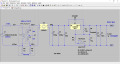
Please find attached Images of diode rectifier ans step by step connections till cap connected.
I have mentioned DC and AC both voltages measured before and after connecting filter cap. Also Diode rectifier connections from AC.

Please guide me if am wrong.

Step1.jpg Step 2.jpg Step3.jpg Step1.jpg Step 2.jpg Step3.jpg Step4.jpg Step5.jpg Step6.jpg
 

Thread Starter

Anubhav Sharma

Joined Mar 21, 2016
68
What you are describing IS full wave rectification. This only requires two diodes on a centre-tap. I am unsure as to how this is designed internally however. While I know putting two parallel dual windings in series will give you the sum of the windings I am unsure how certain centre taps are wound when they use split-phase power on the secondary's. Putting this is series may leave your circuit with no reference to ground. But as I say I am unsure, if someone who is more knowledgeable about split-phase windings in transformers sees this please weigh in. :)

Oh sorry, i mentioned that as half wave rectifier, but thats what i tried and worked well. I have seen other schematics where +/- 12v wires goes to both AC ends of rectifier and works great.
Please see the latest rectifier connection pictures uploaded and guide me if am doing something wrong.
 

Thread Starter

Anubhav Sharma

Joined Mar 21, 2016
68
Hello again,

You could try using just ONE SIDE of the transformer from the centertap to one other terminal as the AC input to the rectifier. This will give you about 18v DC for testing.

It is starting to look like your rectifier is not connected properly. If you can post a couple pics of that it would help.

I will restate the test voltages with the various test resistors, the lower resistor, and again assuming the 220 ohm output to ADJ terminal resistor (the upper resistor).

220, 2.5v
1.1k, 7.5v
2.2k, 13.75v

Note that these voltages are typical but should be fairly close, and with 18vdc input you should be able to see all three of these if the circuit is working right. If any of these voltages is HIGHER then something is WRONG again.
For example, with 18vdc input and 1.1k if you see 15v output THAT IS NOT RIGHT and something is wrong again.
If you use 2.2k and see 17v output THAT iS NOT RIGHT EITHER and something is wrong.

So if you could post a few pics of your rectifier circuit we can probably help more here. Be sure the pic's show the diodes and the bands on the diodes and the wiring.
Sir please see latest rectifier connection pics i have uploaded.
Thanks.
 
The AC voltages are measured where? They make no sense.

the 2x.x and 3x.x; the second is believable. The first is not.

The breadboard is not designed to handle a lot of current.

Put some sort of resistive load on the DC supply. 50 mA even.

I'm HOPING that that this should make the measurements make more sense.

Vout should be about 12*sqrt(2)-2*Vd +-20% or 24*sqrt(2)-2*Vd +-20%

Vd is a mysterious number that can be around 0-6 to 0.7 Volts.

Accounting for transformer regulation and utility regulation.

1. Put some sort of load on the unregulated DC.

2. The measurement of the 1.2V across the low value resistor is an important one to make.

3. Totally baffled about the AC voltage numbers. a) I don't know where they came from.

4. There is a minimum load value imposed on the regulator. Usually the proper selection of the low value resistor fixes that. Usually there is no regulation at all.

5. Some limiting of Vin should be used. A ZNR for instance in your final version.

6. The two protection diodes should be used in the final version.

7. The breadboard construction scares me.

I forget which regulator you are using. The three terminal regulators except the -HV version have like 1 37 V limit for Vin. The spec is max differential of 40, but the regulator drops about 3. The negative and positive regulators have different pin outs. The small bypass caps ch=lose to the regulators are important.
 

Alec_t

Joined Sep 17, 2013
14,330
It is pointless to try measuring the voltage across the smoothing capacitor or DC side of the rectifier with the meter set to an AC range. The meter is not designed for that and will give a stupid reading (52.3 and 81.9).
 

MrAl

Joined Jun 17, 2014
11,494
Sir please see latest rectifier connection pics i have uploaded.
Thanks.

Hi again,

Ok very good, i must have missed those pics somehow.

In any case, it looks like the power supply transformer and rectifier is wired correctly, but it's hard to tell if you use the center tap of the transformer for any tests. Did you?

The AC measurements you are seeing are obviously fictitious. The cheaper digital voltmeters use the "crest factor" method to measure AC voltages and dont use any AC coupling hardware. They assume that the input is a sine wave that passes through zero, and there is no DC offset. Since your cap voltage is entirely DC, the meter takes the average and so the meter thinks that this is the average value of a sine wave and applies a correction factor. Obviously it's not correct.
The way to correct this problem with a cheap meter is to use a capacitor of value say 0.1uf in series with one of the meter leads when measuring AC voltages riding on a DC voltage. That at least helps to make some sense out of the reading because the cap blocks the meter from seeing the DC and only lets it see the AC part. For example that would help see the ripple voltage on the meter. With no load however there should be no ripple, so if this test shows AC voltage with no load there could still be something wrong.

The DC readings dont look too bad, but please specify if you tried only using half the winding of the transformer for lower DC output from the rectifiers. That would be better to test with.

Also, add a protection diode from output to input across the LM317 as shown on the data sheet. Check for the second protection diode also and add that perhaps. This is important to help prevent the LM317 from blowing out.
 

Thread Starter

Anubhav Sharma

Joined Mar 21, 2016
68
What is weird is the OP mentioning negative voltages.

It a amazes me that an update schematic has been not produced and most of the thread is riding on words.
I have already posted schematics in the starting of thread and the updated schematics is the same as on datasheet and is again on the post.
 

Thread Starter

Anubhav Sharma

Joined Mar 21, 2016
68
The AC voltages are measured where? They make no sense.

the 2x.x and 3x.x; the second is believable. The first is not.

The breadboard is not designed to handle a lot of current.

Put some sort of resistive load on the DC supply. 50 mA even.

I'm HOPING that that this should make the measurements make more sense.

Vout should be about 12*sqrt(2)-2*Vd +-20% or 24*sqrt(2)-2*Vd +-20%

Vd is a mysterious number that can be around 0-6 to 0.7 Volts.

Accounting for transformer regulation and utility regulation.

1. Put some sort of load on the unregulated DC.

2. The measurement of the 1.2V across the low value resistor is an important one to make.

3. Totally baffled about the AC voltage numbers. a) I don't know where they came from.

4. There is a minimum load value imposed on the regulator. Usually the proper selection of the low value resistor fixes that. Usually there is no regulation at all.

5. Some limiting of Vin should be used. A ZNR for instance in your final version.

6. The two protection diodes should be used in the final version.

7. The breadboard construction scares me.

I forget which regulator you are using. The three terminal regulators except the -HV version have like 1 37 V limit for Vin. The spec is max differential of 40, but the regulator drops about 3. The negative and positive regulators have different pin outs. The small bypass caps ch=lose to the regulators are important.
I am using lm317T.
The reason behind showing AC voltage is to ask why connections after bridge is showing AC voltages as there should be no AC after bridge.
On the other hand when i replaced Diode bridge with a Module bridge. module version shows no AC volts. Which one is correct?
Ill test with the points you mentioned and will update here.
 

Thread Starter

Anubhav Sharma

Joined Mar 21, 2016
68
Hi again,

Ok very good, i must have missed those pics somehow.

In any case, it looks like the power supply transformer and rectifier is wired correctly, but it's hard to tell if you use the center tap of the transformer for any tests. Did you?

The AC measurements you are seeing are obviously fictitious. The cheaper digital voltmeters use the "crest factor" method to measure AC voltages and dont use any AC coupling hardware. They assume that the input is a sine wave that passes through zero, and there is no DC offset. Since your cap voltage is entirely DC, the meter takes the average and so the meter thinks that this is the average value of a sine wave and applies a correction factor. Obviously it's not correct.
The way to correct this problem with a cheap meter is to use a capacitor of value say 0.1uf in series with one of the meter leads when measuring AC voltages riding on a DC voltage. That at least helps to make some sense out of the reading because the cap blocks the meter from seeing the DC and only lets it see the AC part. For example that would help see the ripple voltage on the meter. With no load however there should be no ripple, so if this test shows AC voltage with no load there could still be something wrong.

The DC readings dont look too bad, but please specify if you tried only using half the winding of the transformer for lower DC output from the rectifiers. That would be better to test with.

Also, add a protection diode from output to input across the LM317 as shown on the data sheet. Check for the second protection diode also and add that perhaps. This is important to help prevent the LM317 from blowing out.
Hi,
I tried using cntr tap wire as ground and and 2 side wires through 2 diodes as full wave rectifier, doing that every thing worked great. POT reduces voltage to 1.2v and to max a 19v, this way all worked well. The only reason i dont want this method because this gives low output max 19v. And i want 32v max.

In the original circuit where am NOT using cntr tap, i tried 2 protection diodes but that didnt worked and blows LM317. What i understood that its only -12v blowing pot and LM317. Why -12v is still there even after rectifier?

Yes i tries using half of the transformers supply that is 0-12v ( 0 as ground ) and this again worked well no LM317 damaging and pot worked well. Only the output voltage cuts to half = 16.7v and that obvious i think.

Testing AC with .1uf in series:

Actually i did not get it.
Removing filter cap and adding .1uf cap, where one end goes to positive and other goes to meter. Negative lead to ground.
If so, i tried that and gets 6.5v in AC. And 4v in DC.

Please specify if you meant something else.

I bought 0-30v transformer but forgot about peak RMS which will lead me beyond LM317t capacity. So ill opt for 0-24 today.
 

Thread Starter

Anubhav Sharma

Joined Mar 21, 2016
68
Can anyone please tell me, How would you design 32v adjustable power supply with 12/0/12 transformer in the same way? I will follow the same schematic or the steps you will guide.
 

eetech00

Joined Jun 8, 2013
3,958
HI

If you buy a 24v transformer, you need to account for losses from the bridge rectifier(2v) and regulator (3v)
Output from a 24v transformer would be about 33.9v Pk, so output of the regulator including losses would
be 28.9v max. So figure max output would be about 28v.
I've attached a diagram.
 

Attachments

atferrari

Joined Jan 6, 2004
4,771
I know you have thrown the towel which is not bad.

If you plan to use the same transformer (why not?), stop saying "12-0-12" (we all know it is) but asume it as a plain 24 V trafo with no center tap.

Do yourself these favors:

a) In the schematic, near the center tap write "NC" (not connected) and resist the temptation to even think of it again.

b) Desolder the wire you have soldered to that awful center tap (which I suspect is the cause of your confusing negative voltages). God knows what were you using it for.

c) Prior starting again, look here and convince yourself (the animation could help) that the center tap, in this case, has nothing to do. Your actual common is what is shown as "-". Yes the "common " pin of the LM317 goes there too. After all your schematic in the OP says so.

d) Tidily reassemble from scratch your components on the breadboard using short jumpers whenever you can.
 

jjw

Joined Dec 24, 2013
823
At some point you had 35V dc after rectifier at capacitor terminals.
If you still have some pots left to burn :), try connecting one at 35V, wiper not connected. If it does not burn, your problem is elsewhere.
If you bought the pots from Ebay, their power rating can be anything.
With 35V input you can get about 32V output voltage from LM317
 

MrAl

Joined Jun 17, 2014
11,494
Hi,
I tried using cntr tap wire as ground and and 2 side wires through 2 diodes as full wave rectifier, doing that every thing worked great. POT reduces voltage to 1.2v and to max a 19v, this way all worked well. The only reason i dont want this method because this gives low output max 19v. And i want 32v max.

In the original circuit where am NOT using cntr tap, i tried 2 protection diodes but that didnt worked and blows LM317. What i understood that its only -12v blowing pot and LM317. Why -12v is still there even after rectifier?

Yes i tries using half of the transformers supply that is 0-12v ( 0 as ground ) and this again worked well no LM317 damaging and pot worked well. Only the output voltage cuts to half = 16.7v and that obvious i think.

Testing AC with .1uf in series:

Actually i did not get it.
Removing filter cap and adding .1uf cap, where one end goes to positive and other goes to meter. Negative lead to ground.
If so, i tried that and gets 6.5v in AC. And 4v in DC.

Please specify if you meant something else.

I bought 0-30v transformer but forgot about peak RMS which will lead me beyond LM317t capacity. So ill opt for 0-24 today.

Hi,

You arent using the center tap are you? You dont need that. You would only use that if you wanted both plus and minus voltages, which you dont want for this project.

Yes i did mean put a 0.1uf cap in series with the voltmeter to make AC measurements, and that usually works because the input of the meters is usually high impedance. If your meter is lower impedance, then you need a bigger cap like 1uf or something.

Since you got it to work with a single side of the transformer now, that means you should be able to get it to work with the full output of the transformer. That is with the two outside wires connected to the bridge rectifiers and the center tap not used.

If it doesnt work then either something is still wrong with the connection of the bridge to the transformer or the LM317 is a fake and can not take the full voltage. That is typically what happens with fake parts, they work but they cant take the full voltage or current. Hopefully they are not fake.

Another way to test might be to string some 9v batteries together in series and use that as the input power source, with no transformer. If you use one you get 9v, two you get 18v, three you get 27v, so you can test pretty high like that with just three batteries. If you get it to work like that then it is the bridge rectifier that has a problem or one of the connections to it. If the LM317 blows then most likely it is a fake. Dont use the pot though, use resistors for the tests again. Use the pot only once EVERYTHING is working properly.
 

grahamed

Joined Jul 23, 2012
100
Hi

It has been mentioned that the meter set on a.c. might lie when connected to d.c. So check it.

Measure that 9V battery I see lying about with the meter set to d.c and then to a.c. Tell us what it says.

The original circuit does not include the protection diodes - these are required if you have a large output capacitor - which you do. These diodes are shown in #37 (which is straight from the datasheet). If these diodes are not present then even a real LM317 will likely blow, and a fake.....

An LM317 can die in 1mS or less, so you had a fault and now you have a fault and a dead LM317 - this can get very confusing.

The secret to success is method. You must start with the simplest circuit - the 24V transformer alone, then add a bridge, then add a cap, etc. measuring each time. At each stage EVERYTHING must be as expected. If ANYTHING is incorrect or unexplained then do not move on.

Breadboards are notorious for bad connections - twisted wires pushed in are a definite no-no. Solder the bridge to the wires, solder the cap to to bridge and so on.

Do not try to follow everybody's advice in parallel and then report your findings in vague way - some of the things you describe are impossible.

Do not be discouraged. This thing can work.

Do not blow any more LM317 by connecting until you are sure everything else is OK.

Do read the datasheet, especially the bit about diodes when using large caps.

When something weird and unusual seems to be happening then then most likely you have got hold of the wrong end of the stick (meaning making a false assumption somewhere).

Nothing I have said here has not already been said in the posts above.
 

vol_

Joined Dec 2, 2015
93
I agree with what has been said above by others. Start working again from scratch, building the project stage by stage, making sure that every stage is doing what you expect. Start a new thread for the second try of building the project from scratch.
Also putting on the breadboard wires' copper gauge without applying solder on them can cause problems, because the connection of the wire with the breadboard its not always guaranteed. And for using caps with your LM you should also use diodes to protect the lm317, as in the schematic here (there are a lot of info in the links of this site):

http://www.eleccircuit.com/my-first-variable-dc-power-supply-1-2v-to-30v-1a-by-lm317/

For us who dont have great experience in electronics theory and building (i refer to me and you) the first reason for not getting what we supposed to is the lack of method, taking hasty conclusions and after the inexperience in the electronics building and theory.
Also you should ask yourself what you need right now. You will use directly your project for 12V? Or 30V? Because if there is no immediate need to have 30V of output, you can built the 2V-16V version that you got it working, solder it on a perfboard, pcb whatever, see if its working as on the breadboard and after claiming that it is good and you have more experience, go on for the 2V-30V version.
Sorry for telling you what to do, but it is what i would do #120 posts later. The first person that can help you is you.

Keep on building!
 
Last edited:

Plamen

Joined Mar 29, 2015
101
Hi every one, This is for the first time am posting thread here and i really hope to get a solution here.
I am trying to make LM317 Power supply for the first time. I designed a diagram on stimulation software and it goes well.
The major problem is when ever i adjust POT, it gets burnt and not showing any effect on output volts. I have already wasted 12 POTs.

Please take a look at schematics attached. I really dont know where am wrong. I am not an experienced person in electronics.
I am using 12-0-12 / 2 Amp transformer, bridge rectifier ( diode version ), 10 K POT ( B 10K SHARP ).

Output volts - 37v. When the pot is at zero mark, circuit still shows 37V but pot got burnt.

Please help me with this problem. Thanks in advance.

View attachment 103673
Petkan:
LM317 can tolerate 40Vmax at its input. With 38Vac (rms) at the rectifier, the cap can reach 1.41 times higher i.e. exceed 40V.
You can damage LM317 (and most likely already have). The current into the pot is limited by the 220 Ohm resistor (the GND pin of LM317 should not source noticeable current). The fact that pot blows indicated that the IC is damaged (excessive GND current).
It is also a good practice to add temporary a ballast resistor in series with the pot to stop losing them.
With pot at 0 the output voltage should be Vref. With a ballast of say 220 R it should double. Once you get the circuit running properly you can remove this ballast resistor if the minimum voltage is too high to your liking.

What's the power dissipation over the pit at 37vout?
 

Marcus2012

Joined Feb 22, 2015
425
Petkan:
LM317 can tolerate 40Vmax at its input.
Sorry to nit pick but that's just the maximum input-output voltage differential attainable by the regulator, which is 40V for the LM317. It can handle considerably larger input voltages, up to a few hundred volts, due to it's floating-mode operation. LM317HV increases this differential to 60V if a greater voltage drop is required.

A more detailed explanation of this is in this app note.

High Voltage Adjustable Power Supplies


Top