LM317 Voltage Drop (IN>Out) Vs Efficiency

Thread Starter

rardi

Joined Jan 17, 2009
5
Hello:

This is my first post on this forum - I only know enough about electronics to get started on something, but not enough to prevent a FUBAR. So please excuse any protocol miscues.

First the situation, then the question further below.

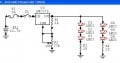
For my sailboat interior lighting, powered by the systems 12 volt deep cycle batteries, I am converting the OEM incandescent 15w bulbs to warm white LED's. Last night I succeeded using a LM317 to provide, from a 12 volt auto battery, a constant 6.4 volts to an array 2 x 3.2v (20 MA each) LEDs in series x 7 in parallel (= 14 total LED's). The LM317 I noticed got very warm, but not overly hot. I decided on the LM317 to regulate, because the source voltage can be from about 14.x volts when the alternator is running, or down to (say) 11.8 volts if the battery bank becomes depleted. Also I wanted enough head room voltage so that the LM317 would provide the constant 6.4 volts.

Question is: Will the circuit be more energy efficient if I set for V(out) to be 9.6 volts (for 3 x 3.2v in series x 5 = 15 LED's) than my arrangement of 2 x 3.2 volts. It would seem to me that the LM317 wouldn't have to dump as much energy in the form of heat: i.e. 12v average Vin to to 9.6 Vout vs. 12v average Vin to 6.4 volts Vout.

Thanks in advance for your advice.

regards,
rardi
 

SgtWookie

Joined Jul 17, 2007
22,230
Hi Rardi,
Sadly, the LM317 is not very energy efficient. It makes for a very simple solution for linear current or voltage regulators, but it is actually very wasteful in terms of power efficiency.

If you've set your LM317 to output 6.4v with a source of 12.7v, then nearly 1/2 of the power is being consumed in the form of heat by the LM317. You would be better off to go for 9.6v (three in series) - but you'll still need 1.7v "headroom" for the regulator itself, plus another 0.5v at least for the current limiting resistors.

Your best bets would be a switching regulator, a buck/boost regulator, or DC-DC converter. They're between 80% and 95% efficient.
 

Søren

Joined Sep 2, 2006
472
Hi,

The most efficient will be a switcher with current feedback.
LED supplies should be current regulated, NOT voltage regulated.
 

SgtWookie

Joined Jul 17, 2007
22,230
I agree with Soeren.

Keep in mind though, each "string" of LEDs will require it's own current regulation.

By this I mean that you cannot put three 20mA "strings" in parallel, and feed them 60mA current. If you do, you will wind up with three burned-out strings of LEDs.
 

Wendy

Joined Mar 24, 2008
23,415
Another way...


Each transistor is a current regulator. You can add more transistor / resistor combinations to add more lights. Since the transistors are absorbing in the neighborhood of under a volt, low power transistors would work just fine (say 2N2222 or 2N4401's). The transistors are current regulators in this configuration, you can reduce the number of LEDs with little effect.
 

Thread Starter

rardi

Joined Jan 17, 2009
5
Thanks the very useful replies, particularly about current limiting being preferable. I will give a rethink, but the situation is that I've got eight fixtures I want to convert. Also on the same 12V "cabin lighting" circuit, there are several other types of fixtures that will require 12v supply. So, each of the eight being converted needs its own voltage or current reducing arrangement, rather than (say) one higher capacity switching regulator supplying the entire circuit. And if I have understood correctly that each series string needs its own current limiting, that's more time/cost/complexity than I was anticipating.

I did observe that the simple LM317 circuit that I made to supply 6.4v to 7 series strings of 2 x 3.2v leds, dropped the voltage of the very old auto battery that I hooked the circuit to from 12.41v to 12.40v over a two hour period. Certainly better than the incandescent bulb. Guess my question now is, notwithstanding that current limiting rather that voltage limiting is preferred, is voltage limiting nonetheless a workable option? Particulary if I modify to 9.6v and less voltage drop over the LM317?

Pardon for just one more question. If I set the LM317 for the exact voltage required by the series (or maybe just 1/10v or so below), do I need a to also add a resistor to the series? The LED calculator I found on line, yields the need for a 1ohm resistor for this scenario, but that might be a default?

Again thanks all for the interest in helping me along. (For interest sake, I decided to try my hand at this project when I noticed this year that stores were stocking warm-white led Christmas lights. I was impressed that each light on its own was quite bright. With 30 leds in each string and 2 Leds in the box as spares and 50% off sales after Christmas, and LM317's at $0.75 each, seemed worth a try.)

regards,
rardi
 

SgtWookie

Joined Jul 17, 2007
22,230
Bill, I simulated your circuit using 2N2222 transistors and 1N914 diodes.
Regulation was fair (21mA to 21.8mA) until the battery voltage dropped to 11.4v, and then LED current dropped like a rock.

In this case, that may not be a bad thing; at 11.4v the battery would be nearly discharged anyway. However, 10mA to 15mA current is flowing through the diodes (depending on battery voltage) as long as it's powered, so that's a fair amount of wasted power.
 

Wendy

Joined Mar 24, 2008
23,415
Which diodes? The 1N4454's (or 1N914) are getting around 1ma. If the LEDs are getting that much current (10ma+) then they are lit. If these are white LEDs then I calculate absolute cutoff is 10.5V plus resistor drop (11.1V), give or take.

I think this is a pretty optimum design for this application. It handles low but sufficient voltages well, heating is minimal, and it will do auto applications well.
 
Last edited:

SgtWookie

Joined Jul 17, 2007
22,230
Which diodes? The 1N4454's (or 1N914) are getting around 1ma.
Nope. The two 1N914's in series drop roughly 1.45v.
I'm using a 10.2v to 14.7v sinewave in the simulation.
(14.7v-1.45v)/1k = 13.25/1000 = 13.25mA.
(10.2v-1.45v)/1k = 8.75/1000 = 8.75mA.
If the LEDs are getting that much current (10ma+) then they are lit.
Sure, but at 50% brightness. But I'm talking about the diodes, not the LEDs.
If these are white LEDs then absolute cutoff is 10.5V plus transistor BE drop (11.1V), give or take.
Did you happen to breadboard this circuit? Mine are full at the moment, and I don't feel like stripping them down.
 

SgtWookie

Joined Jul 17, 2007
22,230
If I have understood correctly that each series string needs its own current limiting, that's more time/cost/complexity than I was anticipating.
Yes, LEDs are current devices. A very small change in voltage across an LED will produce a very large change in current; not only that, but each LED has a slightly different Vf (forward voltage).

I did observe that the simple LM317 circuit that I made to supply 6.4v to 7 series strings of 2 x 3.2v leds, dropped the voltage of the very old auto battery that I hooked the circuit to from 12.41v to 12.40v over a two hour period. Certainly better than the incandescent bulb. Guess my question now is, notwithstanding that current limiting rather that voltage limiting is preferred, is voltage limiting nonetheless a workable option? Particulary if I modify to 9.6v and less voltage drop over the LM317?
When used as a voltage regulator, the LM317 will drop a minimum of 1.7v across itself (Vin-Vout >=1.7v); this is known as the "dropout voltage".
You will also need at least 0.5v headroom for individual current limiting resistors, as even though the LM317 regulation is quite good, the individual LEDs will have variations in their Vf - and the Vf will actually change over temperature. The warmer they get, the lower the Vf, which increases the current, which heats them up more... this is a condition known as "thermal runaway".

So, 9.6v for the LEDs + 0.5v for the current limiting resistor + 1.7v for the LM317 means 11.8v minimum battery voltage.
The current limiting resistors can be 25 Ohms, since 20mA across 0.5v = 25 Ohms.

There are "low dropout" regulators available; some of them have as little as 0.4v drop across themselves.


Pardon for just one more question. If I set the LM317 for the exact voltage required by the series (or maybe just 1/10v or so below), do I need a to also add a resistor to the series? The LED calculator I found on line, yields the need for a 1ohm resistor for this scenario, but that might be a default?
That won't work, due to the variations in LED Vf in the batch, and over temperature.
 

Wendy

Joined Mar 24, 2008
23,415
I see what you're saying. I misplaced a decimal place on the bias resistor. I figure a 4.7KΩ would also work (2.2ma), and drive up to 6 or so LED legs. The 1KΩ will feed up to 36 or so legs. It will probably be less, I would have to try it to be sure.

The basic idea is sound though. Variations in LEDs don't matter with a constant current source.

****************

Went through the math, 10KΩ should handle 2 or 3 legs.

BTW, what are some of these newer voltage regulator part numbers?
 
Last edited:

SgtWookie

Joined Jul 17, 2007
22,230

Thread Starter

rardi

Joined Jan 17, 2009
5
Dear SgtWookie:

Again thanks ...

I now understand the need for the current limiting resistor for each series of 3 LEDs. I don't anticipate the battery voltage getting below 11.8v (in which case I probably would have more concerns about the state of my electrical system than maintaining optimum LED function -- such as having enough power to get the diesel engine start.)

But so I'm sure (and I apologize for not fully absorbing the principles), do I:

a) set the LM317 Vout to 10.1v = 9.6v (for the 3 led's in the series) +.5v (for the 25ohm current limiting resistor);

or

b) set to 9.6v for the 3 led's + the 25 ohm resistor.

I'm guessing a) is the answer!

regards,
rardi
 

SgtWookie

Joined Jul 17, 2007
22,230
OK, let's go through it. :)
Each of your LEDs has a nominal Vf of 3.2v @ 20mA.
3 times 3.2 = 9.6v
Now, you'll need at least 0.5v for the current limiting resistor (this is actually a bit tighter than I prefer to go, but LM317's are quite stable regulators)
9.6v + 0.5v = 10.1v - that's what you'll need to set your LM317 output voltage to.

The current limiting resistor is 0.5v/20mA = 25 Ohms.

As has already been mentioned, the LM317 has a minimum 1.7v dropout voltage.
10.1 + 1.7 = 11.8v. As soon as your battery voltage drops below 11.8v, your LEDs will begin dimming.

You can use an LM317L if you wish to save space. These are available in a TO-92 case, which is much smaller than the TO-220 case that the LM317T comes in. They are limited to 100mA maximum output current.

See the attached schematic.
R1 will result in a nominal 1.25mA current flow from the OUT terminal to the ADJ terminal.
The 10k pot allows adjustment of the regulator's output voltage.

When you assemble the circuit, set the 10k pot to about the halfway position. Adjust to 10.1v output with 12v applied to the input.

http://www.Digikey.com is a good parts source for hobbyists, as they don't have a minimum order, and they will ship SMALL orders via USPS 1st Class, which will save you money.
 

Attachments

Thread Starter

rardi

Joined Jan 17, 2009
5
Dear SgtWookie:

You been extremely patient with me ... many thanks. The way forward, and the logic, is very clear now.

Thanks for the tip about the 317L's. However, I already have LM317T's. There's enough space for one inside each fixture plus room for the resistors and the LED's. Appreciate the DigiKey link.

I've had my already made but-to-be-modified-per-your-suggestion circuit again running now for 5 hours from the old auto battery. Hope that this configuration hasn't shortened the life of the LED's by too much. I guess because the sun is now shining through my garage window and warming the battery temperature, the battery's voltage has actually increased over the time from 12.40v to 12.42v. Even though the LM317 set up to regulate by voltage isn't as energy efficient as other options, the LED modified fixtures will nonetheless use a fraction of their incandescent version. Each fixture won't put out as many lumens, but I can now turn a few on around the boat's cabin, rather than just one, and still use less energy.

You've all been a great help.

rardi
 

SgtWookie

Joined Jul 17, 2007
22,230
Dear SgtWookie:

You been extremely patient with me ... many thanks. The way forward, and the logic, is very clear now.

Glad that helped :)

Note that for general use as a voltage regulator, an LM317T requires a minimum of 10mA current for guaranteed voltage regulation. Since even one string of LEDs will provide the required current draw to guarantee regulation, we can use much larger values for R1 and R2 that are typically required for a general purpose power supply; 120 Ohms being a standard value for R1.

Thanks for the tip about the 317L's. However, I already have LM317T's. There's enough space for one inside each fixture plus room for the resistors and the LED's. Appreciate the DigiKey link.
Those will work just fine, as long as there is room for them.

I've had my already made but-to-be-modified-per-your-suggestion circuit again running now for 5 hours from the old auto battery. Hope that this configuration hasn't shortened the life of the LED's by too much. I guess because the sun is now shining through my garage window and warming the battery temperature, the battery's voltage has actually increased over the time from 12.40v to 12.42v.
This is a bit unusual, since generally a lead-acid battery's voltage will drop as the core temperature increases.

Plate sulphation begins when the battery voltage is at around 12.5v or less at 77°F. Make sure to recharge your battery ASAP to prolong it's life.
Even though the LM317 set up to regulate by voltage isn't as energy efficient as other options, the LED modified fixtures will nonetheless use a fraction of their incandescent version. Each fixture won't put out as many lumens, but I can now turn a few on around the boat's cabin, rather than just one, and still use less energy.
Some of the power will be dissipated in the LM317, but for a deep-cycle lead-acid battery, the drain is practically negligible. A size 24 deep-cycle battery rated for 80AH (20-hour discharge rate) could run five 20mA strings of LEDs for 210 hours (nearly 9 days) before becoming 30% discharged.
 

Søren

Joined Sep 2, 2006
472
Hi,

Just for the heck of it, here's a 15 LED lamp with a linear discrete current regulator.

Since it haven't been build (yet), please enlighten me, should you find any blunders. I seriously believe that me and my pal (Jack Daniels) have ruled them out here tonight though, but then again, he can be a devious guy ;)


Oh, here's the link: 12V LED Lamp
 
Last edited:

SgtWookie

Joined Jul 17, 2007
22,230
It works in simulation, but LED1 or LED2 could be an Achilles' heel if either of them opened up. That would cause the rest of the LEDs to get maximum current flow through them; then they would all have to be replaced. If LED3 failed open, all the other LEDs would simply turn off.

Other than that, if LED1 through LED3 represented the median Vf of the remaining LEDs, it would work pretty well - even if multiple failures occurred in the other strings.
 

Thread Starter

rardi

Joined Jan 17, 2009
5
Dear SgtWookie:

Just to report that I did complete the LED circuit you advised with what looks like the desired success.

With less voltage drop across the LM317, from 12.5-12.8v (or so) to 10.1 volts, compared to my original Vout of 6.4v, its hard to even detect any warmth on the LM317. I checked the voltage drop across each of the 12 diodes in the array. The highest was 3.2v (the rating for the diodes), and most were 3.16-3.18 volts...pretty darn close. The 12 diodes put out a respectable amount of light.

Now, back to the soldering to complete the other seven units, and then back to the boat to re-install the now energy efficient fixtures.

Thank you for all your help. I learned something and the project will have on-going benefits.

regards,
rardi
 

SgtWookie

Joined Jul 17, 2007
22,230
Ok, so you're using four strings of three LEDs in each light. That should be fairly bright.

The total current used by each lamp will thus be 4 * 20mA+1.25mA (for the ADJ circuit)
Each 25 Ohm resistor will dissipate 0.5v * 20mA = 10mW of power, total 40mW.
The 1k resistor will dissipate 1.25v * 1.25mA = 1.5625mW power.
When your battery is fully charged (roughly 12.7v or so) the LM317 will dissipate (12.7v-10.1v)*81.25mA = 2.6v*0.08125a = 211.25mW power.
So, 40mW+1.5625mW+211.25mW= 252.8125mW power "overhead" per lamp assembly.
Meanwhile, 9.6v*80mA = 768mW power consumed in the LEDs.
This means that your lights will be about 75.3% efficient with a fully charged battery. Not too bad for a linear regulator, if I say so myself. :) Each lamp will dissipate a total of 1.02 Watts of power.
A standard 1156 automotive bulb dissipates around 27 Watts of power.
 
Top