LM317 Vin-Vout < 3V in constant current source

Thread Starter

andrei.mita

Joined Jun 19, 2018
25
This thread is actually a fork from a previous one where some good people suggested I should use a constant current source instead of a regulated voltage to read the resistance from an automotive sender (actually 3, 2 NTC temp senders, 1 oil pressure).

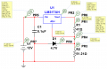
While I wait for the parts I went through the LM317 datasheet, did some math on paper and finally simulated the whole thing.

The resistance of all senders in the working range are great, no issue there. The problem comes when it's -20 degC outside. Any of the two NTC senders will be around 5kOhm. With my current setup, LM317 set to output 27mA, the voltage becomes 135V.

I assumed that can't happen so I did a quick simulation to check the results. And I noticed that at a very specific point the constant current starts to drop and the voltage over the temp sender will never ever get to 135V.

That very specific point is actually when Vin-Vout drops bellow 3V.

Then I noticed the following line in the datasheet: 3 V≤(VIN−VOUT)≤40 V

But I don't know how to understand it. This isn't the drop-off voltage. It's supposed to be 1.5V
So, where does the 3V comes from and what happens when Vin-Vout<3V

The second question is about the zener diode used to limit the voltage that goes to the Arduino. It also solves the issue of a very high resistor. But is there any downside of using it? Is there a better alternative?

And finally, is there a downside to using a constant current source to measure the resistor? It seems much elegant now to me, but when it comes to NTC sensors, the entire internet will advice you to go for a classic voltage regulator and a voltage divider (and theoretically even the ccs is still is a voltage divider).

Thanks,
Andrei
 

Attachments

ebp

Joined Feb 8, 2018
2,332
Two things come into play - the minimum required input to output voltage differential and the fact that the 317 regulates the voltage between the output and the ADJ pin at 1.25 volts. When you use the device as a constant current source, you have to have the sum of those two voltages, at a minimum, between input and output [EDIT - output here meaning the "final" output of the current source, which is actually the ADJUST pin].

If the load won't permit the set-point current, the pass transistor in the 317 will be "fully turned on." This can lead to a bit of a transient overshoot of current if the load is very abruptly reduced to where current regulation is expected, but with your sensors the probability of this is going to be indistinguishable from zero. It might be something to be considered if the load were switched in an out of circuit at high slew rate. This isn't unique to the 317 and will occur with other regulators or references. The 317 uses a Darlington pass transistor and Darlingtons are generally slower to turn off than simple transistors.
 
https://www.onsemi.com/pub/Collateral/LM317-D.PDF#page=5
Figure 8.

Then add the 1.2 V across the set resistor for the CC source and you get 3 V.

So, the differential voltage has to be above 3 V which depends on temperature. What happens below that is anyone's guess, but you don;t get regulation. Don;t know where your getting 135 V.

In your old thread I recomended the LT3092. Here http://www.analog.com/media/en/technical-documentation/data-sheets/3092fc.pdf#page=4 your looking at a dropout voltage of around 1.6 volts.

www.protoadvantage.com can mount digi-key part numbers on an SMT to DIP adapter for you if you can't so the part is easier to work with.


Your supply voltage is a "compliance voltage". It can't exceed that - some voltage related to temperature and the amount of current drawn and parts variation.
 

crutschow

Joined Mar 14, 2008
34,412
The resistance of all senders in the working range are great, no issue there. The problem comes when it's -20 degC outside. Any of the two NTC senders will be around 5kOhm. With my current setup, LM317 set to output 27mA, the voltage becomes 135V.
Obviously you can never get to more than about 3V below the supply voltage with the LM317 so, for 27mA, the maximum resistance you can detect will be about (13V-3V)/27mA = 370Ω.
That should work fine for the pressure sensor.

But, if you need to detect more than that for the NTC sensors, then you may have to go to a voltage source or bridge circuit for those.
This will give a non-linear output with change in resistance but will still allow you to detect the high resistance at low temperatures.

Alternately you go use a constant-current that would give no more than 10V at the maximum resistance, but that my give you a very low signal voltage at room temperature or above.

What is the resistance range you want to detect?
 

ebp

Joined Feb 8, 2018
2,332
Protecting analog inputs can be quite difficult.
What is the minimum operating voltage of the Arduino?
Is the reference voltage for the A to D converter the same as Vdd for the processor, or something less?
If the ref is equal to the supply voltage, can you tolerate losing a bit of range at the top end?
Is there any reason that using op amps as part of the protection scheme would be unacceptable?

Some things for you to check in the processor data:
Is there a specification for the maximum allowable current into the input protection diodes?
Is there a recommendation for maximum source impedance for an analog input?

In general, true zeners are not what we might wish for (what we call zeners are true zeners below about 6 volts and avalanche diodes above that - of course avalanche diodes have to be the ones with the better characteristics for clamping). All of them have rounded "knees" in the voltage-current plot, so they start conducting a bit of current below nominal voltage, which is the main issue, and it is worse with zeners than avalanche diodes.
 

ebp

Joined Feb 8, 2018
2,332
I just noticed that several of the figures in the TI datasheet are still grotesque messes (wrong titles, wrong labels on axes, etc,) after several years of being that way. I think it is less bad than it was when the first really badly done rev was released several years back (arrival of color corresponded with arrival of awfulness).
 

Thread Starter

andrei.mita

Joined Jun 19, 2018
25
https://www.onsemi.com/pub/Collateral/LM317-D.PDF#page=5
Figure 8.

Then add the 1.2 V across the set resistor for the CC source and you get 3 V.

So, the differential voltage has to be above 3 V which depends on temperature. What happens below that is anyone's guess, but you don;t get regulation. Don;t know where your getting 135 V.

In your old thread I recomended the LT3092. Here http://www.analog.com/media/en/technical-documentation/data-sheets/3092fc.pdf#page=4 your looking at a dropout voltage of around 1.6 volts.

www.protoadvantage.com can mount digi-key part numbers on an SMT to DIP adapter for you if you can't so the part is easier to work with.


Your supply voltage is a "compliance voltage". It can't exceed that - some voltage related to temperature and the amount of current drawn and parts variation.

Yes, adding the 1.25 that is regulated pretty much solves the mystery. How did I missed that?
135V comes from a 5kOhm resistor at 27mA.

I don't know how I forgot the info about LT3092. I have yet to review the entire thread post by post, I got so much fantastic information in there that I have to print it out and go through it line by line. I'm not actually concerned about the dropout voltage, there is plenty to work with. The car battery should sit at 12.4V, 13.4V with engine running, and I can't and don't have any use for anything above 4.5V. But LT3092 looks like another fine alternative, and as I'm still experimenting this works great for me.
 

Thread Starter

andrei.mita

Joined Jun 19, 2018
25
Obviously you can never get to more than about 3V below the supply voltage with the LM317 so, for 27mA, the maximum resistance you can detect will be about (13V-3V)/27mA = 370Ω.
That should work fine for the pressure sensor.

But, if you need to detect more than that for the NTC sensors, then you may have to go to a voltage source or bridge circuit for those.
This will give a non-linear output with change in resistance but will still allow you to detect the high resistance at low temperatures.

Alternately you go use a constant-current that would give no more than 10V at the maximum resistance, but that my give you a very low signal voltage at room temperature or above.

What is the resistance range you want to detect?
I totally failed to explain this properly.
The pressure sensor has a range of 10Ohm at 0bar to 184Ohm at 5bar. Oil pressure with the car running should be between 1 and 2 bar, 47-82Ohm. More than fine here. Resistance can't go above 184Ohm because the engine will explode long before this happens (it actually did).

The oil temp. sensor works between 60degC(221.17Ohm) and 120degC(36.51Ohm).
The water temp. sensor works between 40degC(291.46Ohm) and 110degC(29.12Ohm).
So I'm also good here except in the winter when I fire up the engine and it's -20degC outside. The resistance of the temp sensors will be anywhere between 4kOhm and 6kOhm. I don't have to read the voltage/temp, but I have to protect the circuit from sending it to the Arduino.

That's the only problem I'm left with (I hope and think). I have added the zener diode so that it diverts the voltage once it's near 4.7V and it really doesn't matter if it's 4.7V, 5V or 4.2V as I'll be constantly reading ~2V in the Arduino.
 

Thread Starter

andrei.mita

Joined Jun 19, 2018
25
Protecting analog inputs can be quite difficult.
What is the minimum operating voltage of the Arduino?
Is the reference voltage for the A to D converter the same as Vdd for the processor, or something less?
If the ref is equal to the supply voltage, can you tolerate losing a bit of range at the top end?
Is there any reason that using op amps as part of the protection scheme would be unacceptable?

Some things for you to check in the processor data:
Is there a specification for the maximum allowable current into the input protection diodes?
Is there a recommendation for maximum source impedance for an analog input?

In general, true zeners are not what we might wish for (what we call zeners are true zeners below about 6 volts and avalanche diodes above that - of course avalanche diodes have to be the ones with the better characteristics for clamping). All of them have rounded "knees" in the voltage-current plot, so they start conducting a bit of current below nominal voltage, which is the main issue, and it is worse with zeners than avalanche diodes.
I'm not sure what's the minimum operating voltage of the Arduino but I'm not concerned out it. The voltage I'm sending to the analog pin has to be between 0 and 5V or 0 and 3.3V depending on the reference I want to use. The 3.3V is supposed to be very accurate while the 5V depends on the source of the Arduino. I'm safe in both cases.

The only reason for not using op amps is my lack of knowledge. If you can point me to the right direction on how to use them to protect the circuit I will definitely do the reading and explore.

The maximum current into the input diodes I think it's 40mA. For the impedance I don't know how to answer but I found this forum post https://electronics.stackexchange.com/questions/67171/input-impedance-of-arduino-uno-analog-pins

And I have now realized, reading other posts, there is a big problem I have neglected to tackle. What happens if I turn the Arduino off before I switch off the sensor. It seems the input pin will do whatever is necessary to power the Mega.
There are a few basic ways to protect:
1) Everything off the same supply
2) A power supply sequencer
3) A resistor that limits the current to 40 mA in your case assuming a zero volt power supply. (really probably 0.3 V, but use 0)
4) Use an Over the Top OP amp powered from the Arduno side such as https://www.mouser.com/new/Analog-Devices/adi-lt6015-amplifiers/

The buffer configuration is easy. Just (-) to out. Then if you want the thing to read 0 when disconnected, you have to provide a path for the input bias current to go. R < Vos/Ib as a parallel path which might be a 1 M resistor. You also need a bypass cap which is usually a 0.1 uF Ceramic close to the power pins of the OP amp.

www.proto-advantage.com can procure and mount a digi-key part number on a DIP adapter for you.
 

crutschow

Joined Mar 14, 2008
34,412
If you posted a diagram of the interface to the Arduino we could better recommend ways to protect it.
It's not that difficult.
A resistor in series with Schottky diodes to V+ and ground will generally protect the input from any over and under voltages (below).
That will protect the input even if V+ (Arduino supply) is zero.
upload_2018-6-24_10-51-37.png
 
Last edited:

ScottWang

Joined Aug 23, 2012
7,398
hen I noticed the following line in the datasheet: 3 V≤(VIN−VOUT)≤40 V

But I don't know how to understand it. This isn't the drop-off voltage. It's supposed to be 1.5V
So, where does the 3V comes from and what happens when Vin-Vout<3V
The LM317 has minimum output voltage about 1.25V(typical), and the 3V is the voltage drop from input to output by LM317 itself, examp : if you want to get the 5V output from LM317 then the input voltage will be like this --
Vin = Vout + 3V
= 5V + 3V
= 8V
So if you want to get a stable +5V output from LM317 then the input voltage Vin(mini) = 8V, when the input voltage less than 8V then the output voltage could be less than 5V.

In the previous thread that you used 78M08 to output +8V voltage and used resistor with zener to get the output voltage for the Arduino, actually you can use 78M05 is more easy and safe for the arduino, what's reason to let you used R+zener?
 

Thread Starter

andrei.mita

Joined Jun 19, 2018
25
If you posted a diagram of the interface to the Arduino we could better recommend ways to protect it.
It's not that difficult.
A resistor in series with Schottky diodes to V+ and ground will generally protect the input from any over and under voltages (below).
That will protect the input even if V+ (Arduino supply) is zero.
View attachment 155000
@crutschow not sure what do you mean by the interface to the Arduino. There is one wire going to the board (PR4 in my schematic) and one wire from the board to ground.

The resistor was what I was think about, an appropriate one to limit the current at 1 or 2 mA.
What is the purpose of the diodes in your schematic? I have used a zener diode before the resistor. I was thinking that is enough to prevent over voltage. How can under voltage happen and what problems can it cause?
 

Thread Starter

andrei.mita

Joined Jun 19, 2018
25
In the previous thread that you used 78M08 to output +8V voltage and used resistor with zener to get the output voltage for the Arduino, actually you can use 78M05 is more easy and safe for the arduino, what's reason to let you used R+zener?
@ScottWang my previous thread and this one also is not about powering the Arduino, but rather about reading the voltage over a sensor (NTC and pressure) with the Arduino. The zener diode is there to prevent the voltage from going above 5V into the analog input pin of the board on rare occasions.

I'm not after a stable 5V, I'm after a constant current that will enable me to read the voltage going up or down with the resistor/sensor. I do have to prevent the voltage from going above 5V. Am I making any sense?
 

ScottWang

Joined Aug 23, 2012
7,398
@ScottWang my previous thread and this one also is not about powering the Arduino, but rather about reading the voltage over a sensor (NTC and pressure) with the Arduino. The zener diode is there to prevent the voltage from going above 5V into the analog input pin of the board on rare occasions.

I'm not after a stable 5V, I'm after a constant current that will enable me to read the voltage going up or down with the resistor/sensor. I do have to prevent the voltage from going above 5V. Am I making any sense?
Sorry, My thought was fixed on get used to used 5.1V zener to protects 5V ADC input(0~5V) and another question is the R2 changing from 51.21Ω to 6K.

V_R2 = 26.7mA * 6K
= 160.2V (in the #1 is 135V)
If Set V_R2 = 2.5V then
I_R2 = 2.5V/6K
= 0.417 mA
But the Vout mini of LM317 is 10mA, so you can use this way.

Another issue is when R2 = 51.21Ω, I_R2 = 0.417 mA
V_R2 = 0.417 mA * 51.21Ω
= 0.02135 V
Arduino using ATMega328P and it has 10 bits ADC from 0~1024, if set 1024 to smaller resolution as 1.024V, so you need to use a op amp voltage amplifier when the R2 is lower as 51.21Ω, you may also need a voltage to current using op amp to get a lower current.
 

Thread Starter

andrei.mita

Joined Jun 19, 2018
25
It keeps the signal voltage to the Arduino from going above the Arduino supply voltage or below ground.
I'm trying to understand your schematic and how it works.
IN is the voltage going to the Arduino and can go from 0 to 10V lets say. How do the diodes prevent over and under voltage and where is the V+ on D2 coming from?
 

crutschow

Joined Mar 14, 2008
34,412
How do the diodes prevent over and under voltage and where is the V+ on D2 coming from?
V+ is the Arduino supply voltage.
So when the Arduino input voltage gets more than a Schottky diode drop above the Arduino supply voltage, the diode starts conducting and clamping the voltage at the level through the resistor.
That should be sufficient to protect the Arduino input.

Similarly if the input voltage tries to go negative, it will be clamped at one Schottky diode drop below ground.
 
Top