 Facebook
 Google
 GitHub
 Linkedin
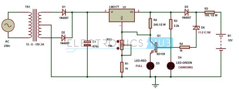
I'm trying to make a charger that can charge two cordless phone batteries.
Each battery is 3.6V NiCD 600mAh.
I used the schematic shown below with these exceptions:
1. The 470uF capacitor is replaced with 22uF.
2. The power source is 12 VDC wall adapter. (everything to the left of the capacitor is replaced with the power supply conector).
3. Both RV1 and R1 replaced with a single 1.8K (1 watt) resistor
4. R2 is replaced with a 330 ohm (1 watt) resistor
5. I used a TIP31 power NPN for Q1.
6. I added a 220 ohm (1 watt) resistor in series with the FULL led to prevent it from blowing up.
7. I made R5 51 ohm (1 watt) resistor to make the charge faster.
8. D5 is changed to 1N4001
9. I tried 1n5232 then in the other test, I tried 1n5235 zener diode.
When I tested things, nothing wanted to blow up, and I had the circuit running for 4 1/2 hours straight and the FULL LED never lit up with the 1n5235 diode.
I did however add a 10K resistor between base of the NPN and common ground. It helped the situation a bit but now the indication is bright for full charge or half-bright light for not charged.
Is there an alternate simplified circuit I can use to detect when two NiCD batteries (7.2V) are fully charged?
") He should be clear that connecting two battery in parallel is a huge mistake, isn't it?
He should be clear that connecting two battery in parallel is a huge mistake, isn't it?


