Facebook
 Google
 GitHub
 Linkedin
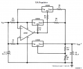
I have lm317t designed with constant current at 1.5A. (just inside specs)
I have designed lm338 designed with constant current at 3A.
This goes to an LED(T6).
Under normal operation I will use the lm317t, however when i push a momentary switch i want it to use the lm338 (go to 3A to the LED).
Can i just put the lm317t in parallel with lm338? then when momentary switch is closed, all the flow goes through the lm338? or will the resistor from the lm317t mess up the calculated lm338 current, or is the design tooo unreliable? [I read you cant use lm317's in parallel to boost Imax with out it getting too complicated] or is it possible the circuits work together to deliver 4.5A?
whats an easy way to use a momentary switch to boost to 3A?

")