Facebook
 Google
 GitHub
 Linkedin
Hi.
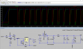
I just installed LM311 pspice files from ti.com. In the attached LTspice XVII file, the LM311 comparator works fine when R6 schmitt trigger hysteresis is removed. When I add R6, I cannot Run the simulation because it almost hangs, runs too slow (might take all day).
The same circuit with R6 added works fine with LM393 or TL1011 comparators. But not with LM311. Any thoughts? Many thanks.
Attachments
-
4 KB Views: 51