LM2577-12 boost regulator.

Thread Starter

GiannisMandelos

Joined Jan 19, 2019
36
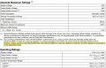
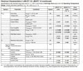
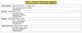
Hi everyone! I need a boost regulator for a DIY of mine that takes an input of about 10Volts and gives a fixed output of 12Volts. In addition, this boost regulator's output current has to be internally limited below 1A. I stumbled across the LM2577-12 and I think that it meets exactly my needs, but I have to get sure. The electrical characteristics of LM2577-12, as well as the circuit are being attached below. One thing I dont get is why should I use only the recommended types of electrolytic capacitors (being attached below as well) and just dont pick my own ones with the exact capacitance as shown at the circuit figure? Finally, it is mentioned that the output current of the LM2577-12 is internally limited down to 800mA when it is used as a flyback or forward converter regulator in accordance to the Application Hints and that is exactly the output current I need. May anyone help me whether should I give it a try or not and what capacitors should I use?
Thank you!!
 

Attachments

ronsimpson

Joined Oct 7, 2019
3,037
Finally, it is mentioned that the output current of the LM2577-12 is internally limited down to 800mA
In the example circuit in the data sheet "Iout=800mA". That is for 5V in to 12Vout.
The IC current limits the internal power transistor current not the output current.
In your case of 10V in to 12Vout I think you can get more current.
There is a complicated link between switch current and output current.
 

Thread Starter

GiannisMandelos

Joined Jan 19, 2019
36
In the example circuit in the data sheet "Iout=800mA". That is for 5V in to 12Vout.
The IC current limits the internal power transistor current not the output current.
In your case of 10V in to 12Vout I think you can get more current.
There is a complicated link between switch current and output current.
Thank you for your response. At the System Parameters, I think it clearly states that for an Input of 5V to 10V we get a typical Vout of about 12Volts accompanied by an output current (Iload) that cannot exceed 800mA (100mA to 800mA). Did I get it wrong?
 

Attachments

Papabravo

Joined Feb 24, 2006
21,225
Yes, the higher the boost ratio the harder the circuit has to work:
  1. 12/5 = 2.4 boost ratio; output current will be input current divided by 2.4
  2. 12/10 = 1.2 boost ratio; output current will be input current divided by 1.2
Things get really dicey at boost ratios greater than 5.
 

ronsimpson

Joined Oct 7, 2019
3,037
I moved to the LT8336 IC because I know it well. Similar part but newer.
At 5v to12V at 1A I see 2.5A of current in the IC.
At 10v to 12v at 1a I see 1.3A in the IC.
These numbers agree with what PapaBravo said.

What we are saying is that at 10Vin you can get your 1A out very easy.
 

Papabravo

Joined Feb 24, 2006
21,225
The #1 immutable rule of ALL DC-DC conversion schemes is this:

The output power of any DC-DC conversion scheme will always be less than the input power; sometimes it will be much less.
Boost ratios in excess of 10, are very hard to actually obtain and so sensitive to small changes that they are also difficult to control effectively. For all practical purposes a boost ratio of 10 or greater is just not feasible.
 
Top