 Facebook
 Google
 GitHub
 Linkedin
Hallo, everyone.
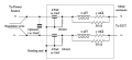
For the schematic of the LISN in attachment, could anyone explain why the Inductance and the resistance are in series and both in parallel with the 50 Ohm Resistor?
Wouldn't it be the same to leave the 50 Ohm resistor, if the objective is to have a constant impedance at high frequencies?
Thanks!
FA
P.S. : Not an electric expert, so hope you would excuse me if the question is silly
Attachments
-
 53.6 KB Views: 36


