Facebook
 Google
 GitHub
 Linkedin
Hi everyone.
This is my first post, I hope you dont mind me making some mistakes along the way or ask stupid questions
I am trying to make a battery discharger for r/c lipos.
Its purpose is to cycle new batteries and discharge any unused batteries for storage..
Lipos are the biggest thing since sliced bread for radio control flying things.
Anyways, there are times when I need to discharge the batts, and since they are high capacity no battery charger with discharge capabilities can load up more than a few amps, if that.
So, I am making a high capacity discharger for batts from 2s (2 cells) all the way up to 8s (8 cells)
The lipos have a min discharged voltage of 3.0 v/per/cell up to 4.2 volts/p/c. ie: min = 2s x 3 = 6v, max = 2s X 4.2 = 8.4v
When using lipos, I discharge the lipos up to 80% capacity.
Therefore 80% of say 5000mAh is 4000mA. This is what manufacturers say to discharge them to. More than 80% and its no good for the batt.
The discharge load will consist of 3 x 55w halogens in series (36v) and 3 x 12v fans also in series but across 7.4v minimum and 36v max..
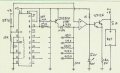
Here is the control circuit

Now comes the bit I need help with. My math is bad so please keep it simple math wise.
Each lipo has different low voltage so I need to be able to select battery cell count.
These I like :
LM339 or similar
TL431 or similar
2s = 7.54 v ~ 8.4 v
3s = 11.31 v ~ 12.6 v
4s = 15.08 v ~ 16.8 v
5s = 18.85 v ~ 21.0 v
6s = 22.62 v ~ 25.2 v
8s = 30.16 v ~ 33.6 v
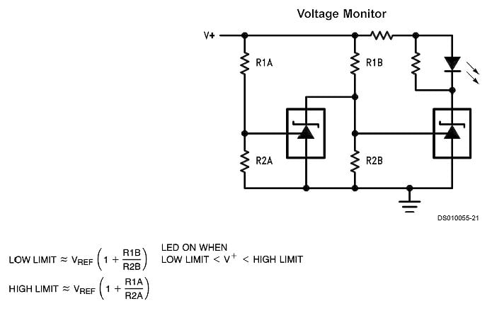
I am thinking Fig 2 or Fig 3 is a cell count circuit which can display an led when the voltage is within its voltage range to show the number of cells
Both circuits are from the makers Datasheet
Fig 2
Using 2 x TL431

OR
Fig 3
Using 2 x TL431
Eg:
3s lipo min discharge voltage of 11.31v up to 12.6v fully charged.
The next lipo say 4s has minimum discharge volts set to 15.08v.
This allows a gap of around 3v so it shouldnt be hard to have a circuit show the number of cells in the battery.
Simply put, the cell count circuit shows a labeled led array the correct cells for a battery.
This concept is fine but I would need 6 of these circuits calibrated to the specific lipo cells. 2s to 8s..
Which ever lipo is connected will only switch the relevant led automatically while the other circuits remain OFF.
******************* Well this is where Im stuck ******************L
Is there a better way to identify 6 different voltage ranges (using led display to show the cell count) ?
==========================
Stage 2
Voltage cutoff
When I plug the battery in, an LED lights up to show the cell count, 2s ~ 8s
So when I press a button for 2s ~ 8s, the circuit will stop discharging at :
Button 1 2s = 7.54v
Button 2 3s = 11.31 v
Button 3 4s = 15.08 v
Button 4 5s = 18.85 v
Button 5 6s = 22.62 v
Button 6 8s = 30.16 v
To prevent the battery from over discharge, some sort of voltage alarm or cutoff is needed
[When the lipo voltage reaches its minimum voltage (see above) it enables a relay and opens a n/c contact (RL3,C1) and stops discharging.]
I have seen many voltage cutoff circuits.
Is there also a more efficient way to monitor a number of voltages, instead of using 6 x voltage cutoff circuits ?
=============================
Other thoughts
1
A transistor circuit might have a too wide switch zone where it might cycle the alarm cutoff on and off.
This is because when the battery load is removed the battery will increase in voltage. (not much though [0.2v ish]
2
Picaxe also comes to mind ????
3
A common relay for the voltage cut off circuits ie: (RL3,C1) normally closed
4
A common buzzer or siren for the cutoff circuit
5
Op amps are ok I guess but I would rather stay with comparators or zener shunts if relevant
Any thoughts greatly appreciated. J
This is my first post, I hope you dont mind me making some mistakes along the way or ask stupid questions
I am trying to make a battery discharger for r/c lipos.
Its purpose is to cycle new batteries and discharge any unused batteries for storage..
Lipos are the biggest thing since sliced bread for radio control flying things.
Anyways, there are times when I need to discharge the batts, and since they are high capacity no battery charger with discharge capabilities can load up more than a few amps, if that.
So, I am making a high capacity discharger for batts from 2s (2 cells) all the way up to 8s (8 cells)
The lipos have a min discharged voltage of 3.0 v/per/cell up to 4.2 volts/p/c. ie: min = 2s x 3 = 6v, max = 2s X 4.2 = 8.4v
When using lipos, I discharge the lipos up to 80% capacity.
Therefore 80% of say 5000mAh is 4000mA. This is what manufacturers say to discharge them to. More than 80% and its no good for the batt.
The discharge load will consist of 3 x 55w halogens in series (36v) and 3 x 12v fans also in series but across 7.4v minimum and 36v max..
Here is the control circuit
Now comes the bit I need help with. My math is bad so please keep it simple math wise.
Each lipo has different low voltage so I need to be able to select battery cell count.
These I like :
LM339 or similar
TL431 or similar
2s = 7.54 v ~ 8.4 v
3s = 11.31 v ~ 12.6 v
4s = 15.08 v ~ 16.8 v
5s = 18.85 v ~ 21.0 v
6s = 22.62 v ~ 25.2 v
8s = 30.16 v ~ 33.6 v
I am thinking Fig 2 or Fig 3 is a cell count circuit which can display an led when the voltage is within its voltage range to show the number of cells
Both circuits are from the makers Datasheet
Fig 2
Using 2 x TL431
OR
Fig 3
Using 2 x TL431
Eg:
3s lipo min discharge voltage of 11.31v up to 12.6v fully charged.
The next lipo say 4s has minimum discharge volts set to 15.08v.
This allows a gap of around 3v so it shouldnt be hard to have a circuit show the number of cells in the battery.
Simply put, the cell count circuit shows a labeled led array the correct cells for a battery.
This concept is fine but I would need 6 of these circuits calibrated to the specific lipo cells. 2s to 8s..
Which ever lipo is connected will only switch the relevant led automatically while the other circuits remain OFF.
******************* Well this is where Im stuck ******************L
Is there a better way to identify 6 different voltage ranges (using led display to show the cell count) ?
==========================
Stage 2
Voltage cutoff
When I plug the battery in, an LED lights up to show the cell count, 2s ~ 8s
So when I press a button for 2s ~ 8s, the circuit will stop discharging at :
Button 1 2s = 7.54v
Button 2 3s = 11.31 v
Button 3 4s = 15.08 v
Button 4 5s = 18.85 v
Button 5 6s = 22.62 v
Button 6 8s = 30.16 v
To prevent the battery from over discharge, some sort of voltage alarm or cutoff is needed
[When the lipo voltage reaches its minimum voltage (see above) it enables a relay and opens a n/c contact (RL3,C1) and stops discharging.]
I have seen many voltage cutoff circuits.
Is there also a more efficient way to monitor a number of voltages, instead of using 6 x voltage cutoff circuits ?
=============================
Other thoughts
1
A transistor circuit might have a too wide switch zone where it might cycle the alarm cutoff on and off.
This is because when the battery load is removed the battery will increase in voltage. (not much though [0.2v ish]
2
Picaxe also comes to mind ????
3
A common relay for the voltage cut off circuits ie: (RL3,C1) normally closed
4
A common buzzer or siren for the cutoff circuit
5
Op amps are ok I guess but I would rather stay with comparators or zener shunts if relevant
Any thoughts greatly appreciated. J