In the first picture in post #23, it appears that you have capacitors connected between the input and adjust of the regulator. This is wrong. The capacitors should be between the input and circuit ground.
A picture paints a thousand words......... there's no capacitor on the regulators output., and the capacitors shouldn't be connected from input to adjust. The whole thing is wrong! Look online for the correct way to use the LM317. Youtube is full of fools!
A picture paints a thousand words......... there's no capacitor on the regulators output., and the capacitors shouldn't be connected from input to adjust. The whole thing is wrong! Look online for the correct way to use the LM317. Youtube is full of fools!
Thank you for such a great reply. I will take all of this in and adjust accordingly. I am a hobbyist, not a professional, obviously. I will get a schematic next time before posting. I just don't have time to make one for a few days. That was my fault. A summary of the setup though is 5 AA LiOn batteries in series for power. I then have resistors reducing the voltage so it can be read properly to the mcp3008. This part is in parallel with the regulator setup. I then have the regulated voltage reduced with resistors and sent to the second analog pin on the mcp3008. I also have the regulated voltage sent as the power for the mcp3008, a sensor, and esp8266, in parallel, meaning they all feed from the same + and - which is 3.15V. The sensor analog is connected to the third analog input for the MCP3008. Wow, that was an ugly paragraph. I will get a schematic asap, but it might be a few days. Sorry in advance. Lesson learned. Thanks! Side note, the sensor needs 3.3 to 5V so maybe it needs a separate power supply. I set my regulator to 3.4V and got the same curves as the plot above though.
Ok that's cool, take your time, most of us are not going anywhere soon
But i did forget to mention something rather important. I don know what your sampling rate is, but if it is fast enough and you dont have to take super fast readings, then you should use averaging to average the measured voltage(s) because that gives you a more realistic measurement, filters out noise, and sometimes actually improves resolution. You could also look into a technique called "oversampling" but that gets a little more complicated and may not be necessary for your app anyway. Since it sounds like you are measuring DC voltages averaging would be a very good idea and it is easy to do in hardware or software or both.
Averaging in hardware means filtering the voltage to be measured with a resistor and capacitor which forms an RC low pass filter.. The R and C for this are determined from what you are measuring and how fast you need each new reading to come in of be logged. This of course means adding another small power resistor and smallish capacitor.
Averaging in software does something similar but you dont have to add any new parts just alter the measuring algorithm slightly. It's actually very very simple and it turns out to be a low pass filter just liek the above but in a digital form using digital sampling concepts. I will illustrate in pseudo microprocessor code.
The simplest is like this, where Va is the measured voltage in digital form which is what you get from the ADC internal to the uC or uP. If you have an 8 bit ADC then you get an 8 bit number that represents the input voltage being measured. You of course divide (or multiply) this number by the factor required for your setup. If you have say a 4.096v reference and your divisor is 256 then each sample level is worth 0.016 volts. So a reading of 1 would mean the input is at 0.016v, and a reading of 2 means 0.032, etc., so a reading of 128 would mean there is 2.048 volts at the input at the time of the sample. You could scale it differently of course and since you have a resistor divider you have to use that factor also. But let's say that we lump all these factors into one calling it "K". Thus, the ADC reading multiplied by K gives you the voltage value, so if you have 2.048v on the input the ADC times K gives you 2.048 in binary.
So now all we do is compute the average. There are several ways to do this but the simplest that also uses low storage resources is the sampled digital technique mentioned above and goes like this...
First, vp is the past calculation and vn is the newly calculated voltage from the new ADC reading...
vn=ADC*K
vp=(vp*(N-1)+vn)/N
and now vp is the reading you take as the 'true' voltage.
This is, in effect, a digital first order low pass filter. It takes several readings and averages them so yo get a more consistent reading. N is a whole number you choose such as 2 through some large number like 1000 but in some cases you may even go higher than that. A typical value though might be 10 or maybe 16.
If we use 10, then we end up with:
vp=(vp*(10-1)+vn)/10
which of course comes out to be:
vp=(vp*9+vn)/10
From this we can see that we are really just weighting the old readings more than the new readings because the new readings may vary too much and so are unrealistic. The reason is a reading that is much more consistent over time.
So as a quick example, let's say the previous reading was vp=9 and the new reading is vn=10, Because the new reading is higher than the previous, we expect the average to go up bu tonly go up a little. The result using N=10 again is:
vp=(9*9+10)/10
which is 91/10 which is 9,1 volts. So it went up a little and this is good. If the new reading is consistent then the number vp works it's way up:
vp=(9,1*9+10)/10=(81.9+10)/10=(91.9/10)=9.19 volts
so notice that it went up more now, and another time:
vp=(9,19*9+10)/10=(82.71+10)/10=92.71/10=9.271
so it went up again, and if the new input stays at 10 it will eventually reach 10. The time to reach about 99 percent of the final vlaue is 5 times the time constant, or the time divided by 5 is the time constant TC.
Now if N=10 does not smooth the output enough, you can use 20, or 50, but keep in mind that the larger N is the longer it takes to settle into the final value.
So this is what low pass filtering does. It makes the readings more consistent in the face of noise and other uncontrollable variations. Before doing that though you should make sure everything else works properly.
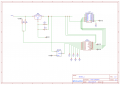
Thanks. Yes, I will be doing the programmatic approach to this. Here is my schematic. VERY IMPORTANT, This schematic is using a HT7333-A regulator NOT the LM317LZ. I realized after posting this that I accidentally used the wrong regulator for this setup. Please let me know your thoughts on the schematic. The power supply can be 1 or 2 CR123A batteries at 3.7V and 800mAh. I am not concerned with battery life just yet as I will eventually put my ESP into deep sleep. For testing the batteries, I am not though. They send data, via WIFI, every 10 seconds.
The schematic looks OK,, but there is a standard protocol for doing schematics which you should learn.
The purpose of a schematic is not just to show connections, but to make it easy to follow the signal flow in a standard format.
It would be much easier to read if you made most of the ground connections vertical, instead of horizontal, minimize wire crossover (such as between the ADC and the ESP), put any resistors in series vertically in a line, instead of side-by-side, and capacitors to ground should also be vertical, not horizontal.
And all active parts should have a unique reference designation (letter and number), the same as the resistors and capacitors.
 Facebook
 Google
 GitHub
 Linkedin