Facebook
 Google
 GitHub
 Linkedin
Hello all,
I have been thinking about this for about three weeks now. There are several issues, but I will ask about one in particular here...
I am trying to design a linear regulator (no LM317, no uA723, ...opamps, resistors, diodes, etc.).
The goal is to achieve 0 - 30VDC at 0 - 3ADC. I would like to regulate both voltage and current, and would like the current-limiting to "kick-in" when the load under power draws more "than it should".
Example: 10 V on load of 10 ohms draws 1 amp. If the current setpoint is 2 ADC, all is well. If I then feed 20 VDC without changing the current setpoint, I would like current to be pegged at 1 ADC.
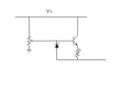
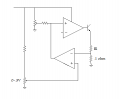
What I have so far is the usual Vref into +Vin on an opamp and I have the -Vin coming from the top of the load back to the opamp. Opamp drives transistor, transistor drives load. This works great. In my actual circuit, the voltage is measured differentially across the load and fed back because of the current sense resistor just below it...
I then (again, differentially) "read the current" via the shunt resistor and another amplifier. Here's where I'm stumped...what design/topology/technique should I employ such that a breach in the current limit pulls the voltage setpoint down until there is no more breach? I've tried a ton of ideas on SPICE, keeping in mind real-world tolerances and issues. I just can't seem to get to the correct solution. It almost seems like I need to dynamically calculate the load resistance in order to determine the associated voltage setpoint change, but I refuse to believe this is the straightforward method.
Any help or guidance would be appreciated!
I have been thinking about this for about three weeks now. There are several issues, but I will ask about one in particular here...
I am trying to design a linear regulator (no LM317, no uA723, ...opamps, resistors, diodes, etc.).
The goal is to achieve 0 - 30VDC at 0 - 3ADC. I would like to regulate both voltage and current, and would like the current-limiting to "kick-in" when the load under power draws more "than it should".
Example: 10 V on load of 10 ohms draws 1 amp. If the current setpoint is 2 ADC, all is well. If I then feed 20 VDC without changing the current setpoint, I would like current to be pegged at 1 ADC.
What I have so far is the usual Vref into +Vin on an opamp and I have the -Vin coming from the top of the load back to the opamp. Opamp drives transistor, transistor drives load. This works great. In my actual circuit, the voltage is measured differentially across the load and fed back because of the current sense resistor just below it...
I then (again, differentially) "read the current" via the shunt resistor and another amplifier. Here's where I'm stumped...what design/topology/technique should I employ such that a breach in the current limit pulls the voltage setpoint down until there is no more breach? I've tried a ton of ideas on SPICE, keeping in mind real-world tolerances and issues. I just can't seem to get to the correct solution. It almost seems like I need to dynamically calculate the load resistance in order to determine the associated voltage setpoint change, but I refuse to believe this is the straightforward method.
Any help or guidance would be appreciated!
")