 Facebook
 Google
 GitHub
 Linkedin
Hi all -
apologies upfront - I have next to no experience/knowledge with electrical design etc - i'm a complete rookie!
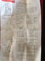
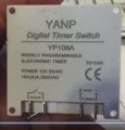
I've followed the diagram supplied by MikeML that outlines how to wire up a linear actuator with a 12V timer and power source to automatically open/close a chicken coop door and it looks like it does work - but i'm having a slight issue and wondering if anybody could suggest what is wrong.
I initially power the circuit and activating the timer the actuator extends fully, and switching off the timer the actuator closes. After that, at approximately every 2 secs the DTDP seems to want to engage the circuit but instantly opens the circuit again - i can hear the actuator's motor receive power but immediately loses it again.
My actuator has built in limit switches and appears to work fine. The entire circuit is 12V.
apologies upfront - I have next to no experience/knowledge with electrical design etc - i'm a complete rookie!
I've followed the diagram supplied by MikeML that outlines how to wire up a linear actuator with a 12V timer and power source to automatically open/close a chicken coop door and it looks like it does work - but i'm having a slight issue and wondering if anybody could suggest what is wrong.
I initially power the circuit and activating the timer the actuator extends fully, and switching off the timer the actuator closes. After that, at approximately every 2 secs the DTDP seems to want to engage the circuit but instantly opens the circuit again - i can hear the actuator's motor receive power but immediately loses it again.
My actuator has built in limit switches and appears to work fine. The entire circuit is 12V.
Attachments
-
 90.9 KB Views: 36
 -
 90.9 KB Views: 35


") .
.


