Facebook
 Google
 GitHub
 Linkedin
NOW IT WORKS!
Hey!... I'm getting good at this...
Hey!... I'm getting good at this...
Attachments
-
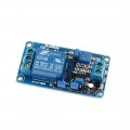
 154.2 KB Views: 49
 -
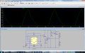
2.8 KB Views: 22
| Thread starter | Similar threads | Forum | Replies | Date |
|---|---|---|---|---|
|
|
Solar Lighthouse With 6 Leds | General Electronics Chat | 9 | |
|
|
My Lighthouse Project | General Electronics Chat | 20 | |
|
|
Off Topic: How to Float a Lighthouse? | General Electronics Chat | 44 | |
|
|
Another lighthouse, inspired by " torpedo chief" | General Electronics Chat | 4 | |
| S | model lighthouse beacon light | General Electronics Chat | 11 |