Light Fixture with Motor, Dimmer Switch, AC DC Inverter

Thread Starter

CB22

Joined Aug 20, 2024
13
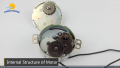
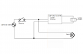
I have a technical question regarding a light fixture I'm building that also has a motor in it. I have geometric shapes that spin slowly around the light fixture light bulbs (almost like a mobile) and this is what I'm using the motor for. The light fixture will be attached to the ceiling like any normal light fixture or chandelier and I want to use a light switch on the wall to be able to turn it on and off. To power the light bulbs and the motor I am using an Inverter which is 12 Volt DC To 110 Volt AC. When you turn the light switch on both the light bulbs will turn on as well as the motor. The question I have is in regards to a dimmer switch. I want to use a dimmer switch to be able to make the lighter brighter or dimmer. However, because the motor is also being controlled by the dimmer switch I want to know if this will be a problem and what will happen. Will it slow down the rotation? Will It damage the motor? If it will pose a problem are there any simple solutions? The motor I'm using is a 12V Synchronous DC geared 1 RPM motor using AC power supply. Any insight or suggestion would be greatly appreciated.
Also, on a side note I'm not sure what inverter I should use for this project. The choice is between a constant current inverter/driver vs constant voltage inverter/driver. I'm not sure which one to use here. Thank you!
 

KeithWalker

Joined Jul 10, 2017
3,603
Is your information on the motor correct? I have not heard of a " Synchronous DC " motor.
If your motor is 12V DC, it will not survive being connected to a110V AC source.
 

Thread Starter

CB22

Joined Aug 20, 2024
13

Thread Starter

CB22

Joined Aug 20, 2024
13
I feel like I left out some information on my first post so just wanted to add more to it to see if that clears up a few things on what I'm trying to do here.

The light bulbs will be powered by 110V AC. The 12V Synchronous DC motor will be powered by 12V DC. I am using an Inverter which is 12 Volt DC To 110 Volt AC which will be able to accommodate turning both the motor and bulbs on with a flick of the light switch on the wall.

The main concerns I have is how this set up will react with a dimmer switch. I want to be able to just power this light on with one wall switch for convenience and I'm only really interested in being able to dim the lights and I'm not concerned about using the dimmer to slow down the motor or anything but because the motor is also being powered by the switch I suppose it will effect the motor also even though I don't want it to. If it will pose a problem are there any simple solutions or work arounds that I maybe haven't though of? It has to look aesthetically pleasing also. Obviously running a power cord from the motor in the light fixture to a wall outlet won't be aesthetically pleasing so I can't do this. Any other suggestions here other than this? I haven't purchased the dimmer switch yet. Is there a certain type that will work with this or a certain type that won't?

Just to clarify why I'm going about it this way. Initially I was just going to use an AC 110 V motor so it would all be on AC. The problem was getting UL approval because of the motor. Because I'm using a 12 V DC motor instead it is kind of a loophole for me so I can get UL approval without all the headaches. Using a 12V DC motor will not be a safety concern in terms of UL certification.

Any insights would be greatly appreciated. Thanks!
 

MaxHeadRoom

Joined Jul 18, 2013
30,562
2 lead DC synchronous motor!?
I am also a little suspicious My guess it has internal electronics, BLDC etc??
Re ad detail: what exactly is '1 x Conversion Module ' ??
 
Last edited:

MaxHeadRoom

Joined Jul 18, 2013
30,562
This is a similar motor, with description that maybe offers the clue.
It would require opening up to get the true picture !

  • Frequency: 50/60Hz ; Power: 1-2W ; Torque: ≤0.5kg.cm ; Rotation: CW/CCW(uncontrollable)
  • Supply voltage DC 12V ; Frequency: 60Hz; Power: 15W;
 

Thread Starter

CB22

Joined Aug 20, 2024
13
2 lead DC synchronous motor!?
I am also a little suspicious My guess it has internal electronics, BLDC etc??
Re ad detail: what exactly is '1 x Conversion Module ' ??
Picture of the inside. They have a video of it running also on the amazon website I sent the link to. Thanks for your reply.
 

Attachments

KeithWalker

Joined Jul 10, 2017
3,603
It is NOT a synchronous motor. It is a geared DC motor. The label on it is incorrect.
That will not affect its usefulness for your project.

Note the last paragraph in the information on the motor:

"*Attention: The applicable voltage of this motor is DC 12V, using AC power supply, the motor does NOT work; too high voltage will burn the motor. If you can't judge whether your power supply is AC or DC, and you have any questions about the voltage, please ask the customer service before buying the motor."

Connect the switch between the DC 12V supply and the inverter and motor, which should be connected in parallel. Connect the 110V AC output from the inverter to the 110V light dimmer. Then when you turn on the switch, the motor, dimmer and light will all operate correctly.

Drawing1.jpg
 

KeithWalker

Joined Jul 10, 2017
3,603
Here is another example of similar motor, obviously there is something going on internally to produce AC !?
I checked the manufacturer's site. I agree, there must be some internal electronics because the motor is brushless. The speed is not dependent on the supply voltage and it can not be used with PWM. I guess we really do learn something new every day!
 

Thread Starter

CB22

Joined Aug 20, 2024
13
It is NOT a synchronous motor. It is a geared DC motor. The label on it is incorrect.
That will not affect its usefulness for your project.

Note the last paragraph in the information on the motor:

"*Attention: The applicable voltage of this motor is DC 12V, using AC power supply, the motor does NOT work; too high voltage will burn the motor. If you can't judge whether your power supply is AC or DC, and you have any questions about the voltage, please ask the customer service before buying the motor."

Connect the switch between the DC 12V supply and the inverter and motor, which should be connected in parallel. Connect the 110V AC output from the inverter to the 110V light dimmer. Then when you turn on the switch, the motor, dimmer and light will all operate correctly.

View attachment 329787
Thanks very much for your informative responses. You did draw the diagram in a way that it could work. The big issue here is that this is in a house and we can not move the switch to make the circuit work. The 110V AC Power supply powers the dimmer switch which than powers both the light bulb and 12 V DC converter in which than powers the motor.
 

KeithWalker

Joined Jul 10, 2017
3,603
I've attached a diagram here that hopefully explains what I'm trying to do here.
That will work, but in your initial posting, you stated : " To power the light bulbs and the motor I am using an Inverter which is 12 Volt DC To 110 Volt AC. "
That is NOT what you are showing in your diagram. It appears that you have been wasting my time in trying to help you!
 

Thread Starter

CB22

Joined Aug 20, 2024
13
Sorry, if you feel I'm wasting your time. I'm not an electrical engineer and my terminology and trying to explain what I mean to people with a lot more experience than me is a challenge. I think the proper term to use is converter instead of inverter. I'm using a converter to go from the 12V DC motor to 110V AC that will power the lights and is standard in most North American houses. This is what I'm trying to say and was not trying to be misleading.
 

KeithWalker

Joined Jul 10, 2017
3,603
Sorry, if you feel I'm wasting your time. I'm not an electrical engineer and my terminology and trying to explain what I mean to people with a lot more experience than me is a challenge. I think the proper term to use is converter instead of inverter. I'm using a converter to go from the 12V DC motor to 110V AC that will power the lights and is standard in most North American houses. This is what I'm trying to say and was not trying to be misleading.
That is not what you show in your diagram. You show the power source as 110V AC Mains.
Is is 12V DC or 110V AC?
 
Top