Lift and lock system for motorcycle jockey wheels.

Thread Starter

Owen Nieuwenhuyse

Joined Jun 20, 2017
42
Current plan is gravity drop, cable/chain pullout, rack or ratchet locking.
This allows a varying lower lock point.
Possible lift drive specs are: 100 lbf pull, 0.2 m/s, about 60rpm at 60mm sprocket diameter.
that is about 460 N, and 460 x 0.2 = 92 W, say 100 Watts?
"Official" winches start in about 1000 lbf, so I need to source a separate clutch unit.

Something that fits on to the gearbox output shaft in-line with the output sprocket would be good.
Output torque is about F x r = 460 N x .03 m = 14 N-m (10.3 ft-lb)
shaft diameter should be around 8mm ? The RobotShop units usually have a "D" form,
with a drive flat.
Any ideas where I can find a nice clutch design or an actual product?
Not having a lathe, I can't make things that require "turning" for now.
It doesn't need a lot of "dog" teeth.

The motor /sprocket shaft extension can be supported by an outrigger bearing.
The clutch needs an inner sleeve or spigot bearing, to locate the output sprocket.

Next: look for a ratchet linear brake/lock?- a small rotary friction brake
usually doesn't have the required torque grip. (to hold the 1200 lbf linear force,
maybe run by chain over 100mm sprockets. - 1 turn= full travel,
torque (5500 N), x 0.05 m = 275 N-m
This would need about a 20mm shaft.
 

Thread Starter

Owen Nieuwenhuyse

Joined Jun 20, 2017
42
Added notes: This looks like it needs the use of a lathe. I will look into it.
20mm y-block cast-iron plummer blocks are heavy and expensive, plus
a half-ton chain is probably 3/4 BS, expensive sprockets?
This is slow enough that greased aluminium shell bearings or bearing blocks would be adequate, but
they need to be custom-made. A 250mm disk brake would be big enough,
or just engage a ratchet with the sprocket teeth! that should have fine enough divisions.
16 teeth? . the motor drive could engage the same shaft. 36 rpm?
A good clutch design could be pins sliding through a driven disk and the output sprocket.
The pins are held in a third sliding disk, propelled by a sliding yoke on a pin shaft.
That in turn is driven by a cable and spring. Can this be simpler?
Swinging yoke, spring return inside the assembly?
This means that the center boss is easily engaged with the "D" shaft on the gearbox,
maybe by a wedge pin? The output sprocket can run straight on a boss extension,
retained by a circlip.

How can the linear drive be engaged by the chain. Can I just use an offset pivot pin
block inserted into the chain, with regular joining links each end?

What about chain tension, side-load on the chain, twisting of the pivot block if it is offset?
Some kind of guide rails may be needed.-the pivot block could have its own slider rails,
side-projecting tabs?

Is this linear system better than a large crank with a 150mm (+ a bit) throw, 1/2 a revolution
full travel? Draw this up for a look. That has twice the shaft torque, will need gearing up/down with
chains or belt drives? Output motion is not very linear.
 

Reloadron

Joined Jan 15, 2015
7,908
Not quite sure what you are asking but a neighbor and I just bought a simple Motorcycle Lift from Harbor Freight on sale for $300 USD. Rather than use their front wheel chock we used one we had similar to this one bolting it to the lift platform. The lift is hydraulic and takes literally a minuite to raise a 900 Lb bike to full height with a foot pump. This thing makes working on bikes a dream, especially because I don't bend as well as I once did.

If I were to design a cycle lift that was powered I would likely use a motorized ball screw with a scissor jack design. Again, not quite sure what you are looking to do?

Ron
 

Thread Starter

Owen Nieuwenhuyse

Joined Jun 20, 2017
42
Not quite sure what you are asking but a neighbor and I just bought a simple Motorcycle Lift from Harbor Freight on sale for $300 USD. Rather than use their front wheel chock we used one we had similar to this one bolting it to the lift platform. The lift is hydraulic and takes literally a minuite to raise a 900 Lb bike to full height with a foot pump. This thing makes working on bikes a dream, especially because I don't bend as well as I once did.

If I were to design a cycle lift that was powered I would likely use a motorized ball screw with a scissor jack design. Again, not quite sure what you are looking to do?

Ron
this is a system similar to "landing gear" for motorcycles. The ballscrew version wasn't looking quite right,
so this is an alternate system, that shouldn't need encoders, microcontroller,motor speed control.

I am looking for off-the-shelf parts I can use. I have a source for small motors and gearboxes now.
I need a light disk brake kit that can take the torque, an in-line micro dog clutch with a "d" type input
shaft socket around 8mm, and a supply of ready-made plain aluminium bearing blocks of various sizes.

I will continue to try dozens of Google enquiries and see if anything comes up, but any knowledge of
existing parts is appreciated.
 

Reloadron

Joined Jan 15, 2015
7,908
This is where knowing ones location helps. I am located in Cleveland, Ohio US and if I want an aluminum bearing block I just do a sketch and any local machine shop can fabricate it for me. Overall I think for the parts you are describing any machine shop and for a disc brake The disc brake and any clutch assemblies I deal with McMaster Carr Supply but again this is US industrial supply. No, I see no need for anything complex like micro-controller.

Ron
 

Thread Starter

Owen Nieuwenhuyse

Joined Jun 20, 2017
42
the wilwood 13A mechanical spot caliper looks like it may be OK.
there are no specs for grip force, but based on the proof load of grade 8.8, 8mm bolts,
(that's what the ones used look like)
and an internal structural leverage of 2:1 apparent, force will max out at 21 kN,
using T = 2 x cof x F x r, a 250mm disk will give a potential torque of 924 N-m.
I need 275 N-m, so there is capacity to spare. (cof = 0.2) The disk is 6.4mm thick,
but the caliper could be modified for a 3mm disk.
 

Thread Starter

Owen Nieuwenhuyse

Joined Jun 20, 2017
42
This is where knowing ones location helps. I am located in Cleveland, Ohio US and if I want an aluminum bearing block I just do a sketch and any local machine shop can fabricate it for me. Overall I think for the parts you are describing any machine shop and for a disc brake The disc brake and any clutch assemblies I deal with McMaster Carr Supply but again this is US industrial supply. No, I see no need for anything complex like micro-controller.

Ron
Being able to de-clutch the drive, using a gravity drop, and a slower lift speed of about 0.5 m/s,
I can then rely on the microswitches to cut the lift motor, and not get excessive overrun torque
from the spinning motor. Maybe the disk brake could be electrically linked to lift, with a car
"cable-pull" electric unit?
The gravity drop should be fairly reliable in finding the actual ground level.
Some trial may be needed to assess tire bounce, and supress it if needed.

the pull-out drag of the chain loop and slider should provide some damping. I may also need a push-out
spring to help overcome mechanism drag.

Getting a nice micro-dog clutch working may require a little research, to work out guiding
and springing requirements. A ready-made solution would be nice.
I will get machining prices for bearing blocks. I expect if I want them nicely milled, bored, and reamed
to size, they will be several hundred dollars each. A dozen of those sort of justifies a lot
of home tooling! ( and some cheapo hacksaw/file/drillpress work) :)
 

Thread Starter

Owen Nieuwenhuyse

Joined Jun 20, 2017
42
Interestinq question: What loading can you get away with for slow speed, intermittent use with transmission chain?
5500 N is 61% of the low uts for 06B1 chain (3/8).
At 60 rpm for 2 seconds at a time,
would this chain be OK without excessive stretching?
Normal faster running recommends
only 9% of the lowest UTS.
Mind you, this cheap chain has a tendency to loosen up the sideplates
if you use it as motorcycle chain, as it is only staked and not riveted at the pin ends.
 

shortbus

Joined Sep 30, 2009
10,049
Interestinq question: What loading can you get away with for slow speed, intermittent use with transmission chain?
5500 N is 61% of the low uts for 06B1 chain (3/8).
At 60 rpm for 2 seconds at a time,
would this chain be OK without excessive stretching?
Normal faster running recommends
only 9% of the lowest UTS.
Mind you, this cheap chain has a tendency to loosen up the sideplates
if you use it as motorcycle chain, as it is only staked and not riveted at the pin ends.
Again like in your first thread on this, you show little sense of mechanical engineering skill. To state things like #35 (3/8" pitch) chain not having riveted pins is just not true.
 

Reloadron

Joined Jan 15, 2015
7,908
He is trying to come up with a set of outrigger wheels to come down and support his motorcycle when he stops at a light or stop sign.
I just generally place my feet firmly down on the deck. Then straddle the bike between my legs. Forgetting to do this can have embarrasing results not to mention leaving me trying to upright about 900 Lbs of bike. Thanks also for the clarification as I was thinking what is a landing gear on a motorcycle? :)

Ron
 

tcmtech

Joined Nov 4, 2013
2,867
Again like in your first thread on this, you show little sense of mechanical engineering skill. To state things like #35 (3/8" pitch) chain not having riveted pins is just not true.
Yep. As with everything else in like the Devil is in the details which for the uninitiated far too often leads to over designing a building one part that does not warrant it while skimming on a highly critical area elsewhere all while not seeing the larger picture of how it all works or does not work together with other things in order to justify what need what and why or why not.
 

tcmtech

Joined Nov 4, 2013
2,867
I just generally place my feet firmly down on the deck. Then straddle the bike between my legs. Forgetting to do this can have embarrasing results not to mention leaving me trying to upright about 900 Lbs of bike. Thanks also for the clarification as I was thinking what is a landing gear on a motorcycle? :)

That's always been my approach given when I learned to ride it was drilled into me that if you can't handle the machine you don't need to be on the road with it for both yours and others safety. Especially if it's with things as simple as keeping it upright while standing still.

I fully support the Darwin awards so I am mostly concerned for others safety here like for driving off with whatever homemade landing gear down (forgotten or just stuck) and crashing into someone because of it. :oops:
 

spinnaker

Joined Oct 29, 2009
7,830
He is trying to come up with a set of outrigger wheels to come down and support his motorcycle when he stops at a light or stop sign.

If that is all it is then it seems to me this is a solution looking for a problem.

Why not just put your feet down like the rest to the world does when riding on two wheels?

or

Buy a trike

or

Learn to track stand a motorcycle. ;)


Last edited:

shortbus

Joined Sep 30, 2009
10,049
Spinnaker, the track stand thing was something I was pretty good at when stopping at a stop sign on my old Harleys. They have a much lower center of gravity than my newer one. When I say old I mean Panheads, a 1957 and a 1958. Didn't ever try the way shown in the video though, just kept both feet on the pegs and leaned which ever way was needed to keep the balance.
 

shortbus

Joined Sep 30, 2009
10,049
Yep. As with everything else in like the Devil is in the details which for the uninitiated far too often leads to over designing a building one part that does not warrant it while skimming on a highly critical area elsewhere all while not seeing the larger picture of how it all works or does not work together with other things in order to justify what need what and why or why not.
There's a way that this could be done, but just not the way he wants. Also I'd never do it to support the whole weight of the bike, just enough to only let it lean slightly, A few degrees from perpendicular, and let the legs do the rest. But I'm assuming he started a new thread putting more numbers and equations in it to sound like he has a better understanding of things. And hoping no one would see.
 

Thread Starter

Owen Nieuwenhuyse

Joined Jun 20, 2017
42
Again like in your first thread on this, you show little sense of mechanical engineering skill. To state things like #35 (3/8" pitch) chain not having riveted pins is just not true.
Well, I don't buy a lot of chain. I have heard that the stuff you can buy on-line is not as good as proper motorcycle chain. I heard about this staking thing second-hand. Similarly with automotive cam chain.
About the only difference is the way it is riveted The ultimate tensile strength looks OK.
 

Thread Starter

Owen Nieuwenhuyse

Joined Jun 20, 2017
42
There are lots of different ways of adding extra stabilizing supports, and many reasons justifying
one method or another. I favour the idea of treating the stabilizer arms/wheels like a narrow trike,
(quad-trike? with a center wheel?)
which I can then turn back into a motorbike. The trike layout is strictly for low speed or round-town use.

I haven't actually posted any mechanism layouts here yet,
but the one I have done looks excessively space-consuming, now that I think about it more.

I have shifted the mufflers out of the way for my new version (and model that I am constructing).
This opens the way to inserting the lift mechanism into the trailing arms, which are quite long.
Either that, or they can be arranged to fold up flat when the arms are retracted, and then project downwards when the arms are deployed.
 

Thread Starter

Owen Nieuwenhuyse

Joined Jun 20, 2017
42
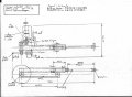
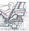
linear actuator 4-7-17.jpg rear side view as at 4-7-17.jpg here are some drawings:
1) side view of jockey wheel area. The bike is of a style called "feet forward", single seater,
built-in upper luggage, semi-streamlined fairing.
The rider seat is a little lower than the average cruiser layout, with a full height seat back.
2) the proposed chain-driven linear actuator. Note that the closed length is 620mm
It could be reduced a little by locating the disk brake on the front spindle.
The motor, 2 gearboxes, and clutch, make it quite wide. A "crossover" drive layout is taller, but not as wide.

A ballscrew unit can be more compact, but cannot be declutched, and needs torque control
and possibly a rotary encoder to get two different speeds, or a close-to-gravity drop.
 
Top