Facebook
 Google
 GitHub
 Linkedin
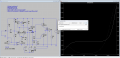
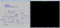
I see what you mean, yes, I was even surprised the output I got doesn't expose any crossover distortion. I believe the negative feedback came as a cure here - whenever the output wants to show some distortion the feedback loop enhances the gain as to oppose this change. Am I right? Do you think I still should add those biasing diodes or voltage multiplier as I had them in earlier posts?Underbiassed refers to the fact that there is no standing current through the output stage, so the Base voltage of the output transistors has to jump to +0.6V before any positive current can flow in the load, and the jump to -0.6V before any negative current flows. There is a dead band in the middle when no current flows.
I am doing some study on the output impedance & pole compensation, will likely come back with some more questions soon
")
Thanks!