Facebook
 Google
 GitHub
 Linkedin
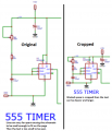
the way my circuit works we have 4 wires that will be connected constant 12v , gnd ,brake signal , dim signal when dim is applied all led light up but dim, when brake is applied each array lights up one after the other and then stays on until the signal is turned off. is this correct
Attachments
-
 48 KB Views: 34