LED Sound Reactive Jumpsuit

Thread Starter

73 Fat Chick

Joined Sep 1, 2010
20
That's what I'm quickly coming to understand, Audioguru.

How many LEDs do you think I could keep lit for 3 hours with 8 D-cell Alkaline batteries?

Or do you have a better idea for achieving the maximum lit LEDs for the maximum time with a battery supply of a reasonable weight and cost? Would I be better off with a 12v 7A lead acid battery? Or would I be better off with some other obscure type of battery wired in series?

In essence, my dilemma is this: Keeping a number of LEDs lit for at least 3 hours with a battery supply that I can carry.

You seem to have a much better understanding of the limitations of this project than I do. I'm interested in any suggestions you might have. Whatever they are... i.e. if you think that it wouldn't be practical to make a costume with more than, say, 10 LEDs, I want to hear it.

Please let me know what you think is a feasible and realistic goal for this project. Once I have a better idea of this, I'll be able to tailor my expectations and goals accordingly.

Thank you for your input!
 
Last edited:

Audioguru

Joined Dec 20, 2007
11,248
If you use many LEDs and operate them very brightly (a high current) then the battery must be big and heavy to last for a few hours.
But is you use fewer LEDs and operate them not very bright then a little light weight battery will be fine or a reasonable battery will last for a long time.
 

Thread Starter

73 Fat Chick

Joined Sep 1, 2010
20
Alright. My lights came in today and I hooked them up to the 12v 7A battery I've got and they all lighted up nicely.

So, after taking gerty's and Audioguru's advice on battery supply, I've decided that I need to try to strike a better balance between the amps being used by the LEDs (hence their brightness) and the size of the battery supply.

By referencing the pdf on Duracell D batteries that gerty posted earlier
(http://www1.duracell.com/oem/Pdf/new/MN1300_US_CT.pdf) it looks like I should be able to get the batteries to last an acceptable length of time (5 to 6 hours) if I reduce the amps being fed into the LEDs by about half (to somewhere between 0.75A to 1.0A.). The voltage drop shouldn't be too bad over this length of time at this current either.

Am I making sense here, or is my logic flawed somewhere?

From what I understand, I can limit the amps going into the LEDs by using a resistor between the LEDs and the battery supply.

Is this correct? If so, how much resistance do I need to lower the ampere draw of the LEDs from 2A to 1A? How much is needed to lower it from 2A to 0.75A?

I know that there must be a formula for this. Can anyone tell me what it is?

Once I figure this out, I'll hook up the LEDs using the two different resistors (the one needed to make it 1A and the other needed to bring it down to 0.75A) to see if the resultant brightness of the LED strips is acceptable. I'll use the lowest acceptable amperage.

Also, a big thanks goes to Audioguru and gerty for their guidance so far. I feel like I've already learned a ton because of both of you. It feels good to finally start bridging the gaps in my knowledge and understanding of electronics.
 

Audioguru

Joined Dec 20, 2007
11,248
Try one LED strip with 8V (eight nearly dead alkaline battery cells) to see if they produce any light because maybe they do not use a current-limiting resistor.
If your battery cells are unused then six will produce 9.0V to 9.6V for you to try.

If they are simply four 3.0V LEDs connected in 75 series strings then their brightness will be severely affected by the battery voltage and dim too much as the battery runs down.

Measure the current of one LED strip because the datasheet says 200mA (20mA * 10) and 2A (24W/12V) for one strip of 300 LEDs.
 

Thread Starter

73 Fat Chick

Joined Sep 1, 2010
20
Ok. I've tested one of the LED strips on three different power supplies:

6 well-used D batteries (7.26v): The LEDs draw 0.472mA - They glow, but barely... Not enough for my purposes.

6 new D batteries (9.36v): The LEDs draw 0.26A - They glow nice and bright... Just right, actually.

1 new 12v 7A Lead Acid Battery (12.59v): The LEDs draw 1.48A - They are blindingly bright (too bright, really... I don't want to be annoying people all night by hurting their eyes with this excessively bright light.)

After examining the wiring of the LED strips, I see that they are composed of 100 "3-LED series wired units" wired in parallel... If that makes any sense at all... How can I put this more clearly? The LEDs are wired in series in groups of three. There are 100 of these "3 LED groups" that are all wired in parallel to one another. Hopefully that makes sense.

I should also mention that the strips are constructed in such a way that I'm able to cut the LEDs off (thus shortening the length of the strip) in groups of three. So I can easily lessen the number of LEDs if this becomes necessary for practicality.

I'm tempted to just leave the LEDs hooked up to 8 new D batteries just to see how long they produce an acceptably bright glow, but I'm not going to get that wasteful unless I get really confused and need to conduct a real world, hands-on experiment.

I like the glow that the LEDs put off with the 6 new D batteries (@ 9.36v and 0.26A).
How can I figure out the best way to reduce the draw on 8 new D batteries to the amperage and voltage similar to that of the 6 new D batteries I tried out in the test above? Also, how can I figure out how much longer this will make these 8 D batteries last (along with a rough estimate of what their overall life span will be)?

Thanks for helping out the biggest damned fool on the whole forum.
 
Last edited:

Audioguru

Joined Dec 20, 2007
11,248
8 new alkaline battery cells are 12.0V to 12.8V.
Since you want 9.36V at 0.26A then a current limiting resistor will have a voltage drop of 12.4V - 9.36V= 3.04V. The resistor value is 3.04/0.26A= 11.69 ohms. Use 10 ohms or 12 ohms at 2W.

When the 12.4V battery drops to 10V then the current and brightness of the LEDs will also drop.
 

marshallf3

Joined Jul 26, 2010
2,358
8 new alkaline battery cells are 12.0V to 12.8V.
Since you want 9.36V at 0.26A then a current limiting resistor will have a voltage drop of 12.4V - 9.36V= 3.04V. The resistor value is 3.04/0.26A= 11.69 ohms. Use 10 ohms or 12 ohms at 2W.

When the 12.4V battery drops to 10V then the current and brightness of the LEDs will also drop.
Why not just use 6 cells? Alkalines are usually 1.6V each when new and stay that way for some time.
 

Thread Starter

73 Fat Chick

Joined Sep 1, 2010
20
That's a good question, marshallf3.

It's my understanding that by using 8 D cells instead of 6 (and limiting the current draw to 0.26A and the voltage to 9.36V), I'll gain longer lifespan from the batteries than I would with 8 (or even 6) D cells with no resistance added.

Is this correct or am I way off-base here?

My goal is to find a happy medium between the brightness of the LEDs and the lifespan of the power supply.

Having acceptably bright LEDs for at least 5 hours would be ideal, but I'm not sure if this is going to be possible.

Again... I'm very new to this, so it wouldn't surprise me if I'm wrong.
 
Last edited:

Audioguru

Joined Dec 20, 2007
11,248
Why not just use 6 cells? Alkalines are usually 1.6V each when new and stay that way for some time.
With six 1.6V cells (9.6V when new) and no current-limiting resistor, the LED current is maybe 300mA. In post #12 the datasheet for a Duracell alkaline D cell was shown and with a 5.1 ohm load (about 320mA) its voltage drops to 1.4V in 3 or 4 hours. Six cells would be only 8.4V and the LEDs will probably be dim.
 

Thread Starter

73 Fat Chick

Joined Sep 1, 2010
20
I hooked one of the LED strips to 8 D cell batteries (setup in series) with a 470 ohm resistor (the only rating that I had on hand) between the batteries and the LEDs. The LEDs are still glowing brightly after six hours of use.

Additionally, I also hooked up the other LED strip to a plain vanilla 9v energizer battery and it's also still glowing brightly after six hours of use.

So my power supply issues are resolved. I'll use two 9v batteries, one on each strip. I'm really pleased with this, as they will be much cheaper, less cumbersome and lighter than carrying around 16 D cell batteries.

Now I've got to wait until my sound activated relay circuit arrives in the mail so I can hook it all up with clips to test the whole setup out.

Hopefully, it works well without much modification, but I have a feeling that it probably won't and this thread will continue to grow.

Thanks for your help so far.
 

Audioguru

Joined Dec 20, 2007
11,248
I also hooked up the other LED strip to a plain vanilla 9v energizer battery and it's also still glowing brightly after six hours of use.
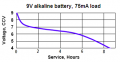
Didn't you look at the Energizer or Duracell datasheet for a 9V alkaline battery? With a load of only 75mA (you said you like the brightness at a current of 260mA) is voltage drops to below 6V (when you said the LEDs were barely visible at 7.26V) in 6 hours.
 

Attachments

Thread Starter

73 Fat Chick

Joined Sep 1, 2010
20
You're right, Audioguru.

But after stressing out so much over the power supply (all aspects... weight, size, as well as output), I guess I subconsciously started to lower in my expectations for brightness.

If it means the difference between carrying around a huge and cumbersome battery supply and a small 9v battery, I'll take a bit of reduction in brightness for the lighter, cheaper battery.

Besides, I think that the data sheet for the LEDs is incorrect because, I just tested the 9v that I used for the test and after six solid hours of use, it still reads 8.33v.

Also, (addressing a concern that came up earlier) after six hours of being lit up by the 9v battery, the LEDs weren't even discernibly warm, much less hot.
 

Thread Starter

73 Fat Chick

Joined Sep 1, 2010
20
My voice activated relay circuit finally came in the mail the other day.

I followed the instructions on the "user manual" sheet that explained how to wire it to accept an electret mic (fairly easy... reverse the polarity of a capacitor and add a 4k7 resistor between the power input for the PC board and the positive side of the mic connection.)

It all functions as it should and I'm really thrilled that it wasn't more of a battle for me to get to this point in the project. There is one thing about the circuit that I would like to modify, however.

When the relay is activated, no matter how I adjust the sensitivity of the circuit (high or low), the relay stays closed for about one second before it opens back up. I would like to have the relay close and the LEDs to light up only as long as the mic is sensing sound. Right now, because the LEDs stay on for one full second each time the mic senses sound, it doesn't really follow the rhythm of the music in any obvious way.

I should mention that the circuit does have one LED built into the board right next to the relay. When the mic senses sound, this red LED lights up brightly and the relay closes (causing my LED strips to light up). The red LED then immediately begins to fade. When the LED has dimmed completely (it takes about one second), the relay opens and my LED strip goes out.

I assume that the fact that this built-in red LED fades (instead of just lighting up and shutting off instantaneously) means that it is connected to a capacitor whose discharge takes about one second. The fact that the relay opens as soon as this LED has gone completely out means that the same capacitor that is feeding the LED is hooked up to the a transistor that is controlling the opening and closing of the relay.

I'm hoping that this modification is something as simple as replacing (or removing) a capacitor or replacing a transistor with one that's more (or less) sensitive to changes in voltage.

I'm sure that this is probably not enough info for you to give me an informed answer on what to do to make the relay operate instantaneously and in real time (by shutting off as soon as the sound stops), but my question to you is: What do I need to provide you in order to get meaningful suggestions and tips on how to modify this thing to make it do what I want?

I don't have a schematic for the circuit, but if it is absolutely necessary, I can probably sketch it out for you. It would probably not be a very fun or easy task, but I'm willing to try if that's my only option.
 

Audioguru

Joined Dec 20, 2007
11,248
The relay might quickly wear out if it "follows the music".

You don't need a relay to turn on your LEDs, you need a transistor which might be the transistor that drives the relay.

But without a schematic and parts list we don't know what delays the turn off and don't know if the relay driver transistor can drive your LEDs.
 

Thread Starter

73 Fat Chick

Joined Sep 1, 2010
20
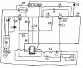
I did my best to sketch the schematic for this circuit.
Sorry that it's so sloppy, but I think that it should be fairly legible.
I'm sure that there are some standard conventions that are used when drawing schematics that I didn't know about and didn't use in this sketch, but please forgive me... This is my first attempt at something like this:

Voice Activated Relay schematic.jpeg

Here's the parts list:

R1= 4k7 (5%)
R2= 1k (5%)
R3= 10k (5%)
R4= 10k (5%)
R5= 10k (5%)
R6= 100 (5%)
R7= 10k (5%)
R8= 10k (5%)
R9= 10k (5%)
R10= 4k7 (5%)

C1= 4.7uF (100v)
C2= 100uF (25v)
C3= 10uF (80v)
C4= 22uF (50v)
C5= 100nK100
C6= 100uF (25v)

D1= IN4007
D2= 1N4148 is my best guess. It's a small orange and black diode marked "PH 4148" but I couldn'y find anything about these exact markings.
D3= A big red LED with no markings other than the flat part for polarity.

RE1= Finder 40.31S Relay "NO" is the "normally open" connection on the relay. "COM" is the common connection on the relay. "NC" is the normally closed connection of the relay.

RV1= PIHER Spain 4M7 Trimmer

IC= TL071CP

MIC= normal electret mic

T1= It's marked "C557B W557" with white mask & any markings on the top were scraped off. One of the transistors listed at this website is my best guess.
T2= It's marked "C547B W83" with white mask & any markings on the top were also scraped off. One of the transistors listed at this website is my best guess.

I didn't include the little arrow that's supposed to be included on the symbol for transistors to dilineate between NPN and PNP types because I don't know how to identify these two transistors.

The way I've got it working right now is that I hook the negative end of the LED strip to the "COM" connection. I hook the positive end of the LED strip to the positive terminal of a 9v battery. I hook the negative end of the battery to the "NO" connection. I use a second 9v battery to power the voice detection circuit.

As I stated in an earlier post, when the circuit is hooked up in this manner, the relay closes when the mic senses a sound, but it stays closed for 1 second. I want the LED strip to stay on only as long as the mic is sensing sound (without this "one second latching.")

The big red LED that's hooked up next to the relay turns on with a sound, but immediately fades over the course of 1 second. Once it's entirely faded, the relay opens again. If the mic senses two sounds within the 1 second, the LED will light up, begin to fade, then light up again with the second sound (and start the 1 second fade again.) The relay stays closed as long as the big red LED is shining at all (for the whole length of the fade.) I wouldn't mind if the LED strips that I'm trying to control with this circuit lit up the exact same way as this red LED does (bright then fade)... The fade looks cool and it "follows the rhythm" in the way that I desire. I wasn't originally planning on making my LED strips fade, but if that's the easier mod, that's more than OK.)

Please let me know if there are any glaring errors or omissions in the above. Also, please let me know if you need me to further clarify anything.

Again, thanks for giving your valuable time to my project and having enough of patience to help a rookie with this. I appreciate everything you've done so far and I'm learning more and more by the day.
 
Last edited:

Thread Starter

73 Fat Chick

Joined Sep 1, 2010
20
After studying the above schematic for awhile I noticed a fairly major error. R7 is not where is should be.

R7 should bridge the two terminals in T1 as is shown above; however, the lead that connects R7 to the right-most terminal if T1 should also be connected to the line between the negative end of D2 and RE1.

I'll try to amend the schematic and repost it with this correction later today.

Sorry about this flub.
 

Thread Starter

73 Fat Chick

Joined Sep 1, 2010
20
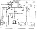
Here's the updated schematic.

Voice Activated relay schematic with correction.jpeg

Now R7 is also connected to the relay control portion of the circuit.

Hopefully, this is the only mistake. I'll keep reviewing my work to look for others, however.

If this drawing is too jumbled to make sense, please let me know and I'll try my best to simplify it.

Thanks.
 
Top