LED sequencing problem

SgtWookie

Joined Jul 17, 2007
22,230
OK, wait a minute.

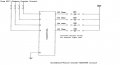
I see that you edited a post a page back (actually, post #48, here: #48), and now you're talking about driving four 7-segment LEDs!

Are you thinking about displaying a time count on there or something?

I hope you realize that the 7-segment displays require a lot more than just four logic lines.

Also, on large 7-segment LED displays like that, usually each "long" segment is made up of four super-bright LEDs that require around 20mA current. You'll have to figure out how much voltage it'll take to get that much current. I have some that are similar to that, and it takes around 11.3v to get 20mA.

Use that LM317 constant current circuit I posted way back to find out what the Vf is.

Note that the decimal points will only have 1 or 2 LEDs in them; they will require much larger resistors to drop the current down.
 
Last edited:

Bernard

Joined Aug 7, 2008
5,784
The inputs to ULN2004[D].looks like 20.7kΩ to ground. Starting at OUT 1, current flows from ground, thru 20.7k thru diode to high out 1.OUT 2,gnd. thru D in 2, thru diode to out 2, or D 1 in up thru diode, left thru diode into high out 2. Skipping to 4, D1 current flows up thru 3 diodes,makes a left into high out 4. Assuming 11V out, minimum V at each input,D, 8.2,8.9,9.6, & 10.3, which should be sufficient for full sinking capability. If using lower V than 12, will take another look. If this ramble does'nt work 'will put numbers on every thing and start over.
 

SgtWookie

Joined Jul 17, 2007
22,230
Bernard, the input resistors on the ULN2004/ULN2804 are a nominal 10.7k.

With a 12v input, the input current will typically be 1mA to 1.45mA.
 

Bernard

Joined Aug 7, 2008
5,784
You are correct Sgt. I was just trying to establish a visual current path from ground to 4017 output. You would have to measure the DC input resistance with a low v [.5v] ohmmeter to get the 20.7 Ω, leaving out base-emitter effects. Did any of the rest make any sense??
 

Thread Starter

Oxbo Rene

Joined Feb 20, 2009
201
OK, Here's the plan......
Bernard, removed LEDs and resistors from circuit and hooked up ULN2004A, put a diode from pin 2 (first output of 4017) to pin #4 as per your drawing, cycled through and it failed (can't recall exactly, just scrubbed experiment when I saw it didn't work), trying to cut down on wasting time experimenting, first sign of failure = abandon, move on.
Made up new circuit drawings keeping "AND" gates and implemented on breadboard = worked.
However,
Calculated limit resistors for LEDs...
LED = 2.6V @ 28ma
2.6/.028 = 92.8 ohms = 100 ohm resistor
Works on breadboard, however,
Voltage measurement across resistor = 8V
Voltage measurement across LED ==== 3V
Figured 8V/100 ohms = 80ma
This says to me that 80ma is also flowing through LED
Where is my mistake ????
----------------------------------
For the countdown "Clock" stuff, have bought a kit-->
Velleman Kit #K8035
Was planning on constructing the kit and just running the appropriate wires to the control console, however, will also want small displays on console as is shown on big board. Of course, will have to amp up values to drive big LEDs, etc.....
-------------------------------------
For the "Score" stuff for "Home" and "Visitors" I was going to use
IC chips ->CD40110B.
See attached for newest drawings.
 

Attachments

Bernard

Joined Aug 7, 2008
5,784
Strange, I have 4 LED's behaving as planned. My 12V is 11V , lowest output to D[ simulated with 4 9.1k's to ground, is 8V. Where did it go wrong? Whitch pin 4 did you use? Anode to pin2, cathode to ULN P4 , out on 14 with LED and resistor? You just gave up too soon.
 

Thread Starter

Oxbo Rene

Joined Feb 20, 2009
201
You just gave up too soon.
Probably so.
Seeing as though you have built it yourself, I certainly will re-visit it, etc
Am trying to finish up the boat burglar alarm, do this stuff, and get stuff done for the ole lady.
Went all over town today looking for some lights for the four "period" lights.
Cheapest LEDs were at Wallmart (orange), $7.00 ea, need 4(X) $7.00 = $28.00 before tax, cheeez.
I bought a couple $2.00 incandescent lights. Checked em out, burn 300ma,
but, ULN2004A drove them no problem. Probably won't use them for the actual deal.
Have searched the web for some Green ones (reflectors) but can't find any the size I need, etc.
Need to return to Skycraft.......
OK, see ya tomorrow,
Oxbo

OK, OK, OK,
Re-doing LED figures =
12V - 2.6V = 9.4V
9.4/.028 = 335 ohm resistor
(Yea, I know, ya don't have to tell me)............
---------------------------------------------------------------------
MY GOD BERNARD ! ! ! ! ! ! ! !
Just went out there (back porch) and re-did your circuit ! !
It works ! ! ! ! !
I can't believe it ! !
All this stuff we been going through, and three little ole diodes did the job, AMAZING ! ! !
Apparently I had something hooked up wrong to begin with.....
Also changed out the 100 ohm resistors with 330 ohm ones.
Now LED reads 2.28V and resistor reads 8.93V
That's more like it.
Sorry for being such an idiot, ain't my fault, my father whipped me when I was a child.......
 
Last edited:

Bernard

Joined Aug 7, 2008
5,784
Congratulations!! Thanks for the credit, but it is'nt my circuit, that belongs to the master, Sgt. Wookie, I only modified it slightly to match changing conditions.
 

Thread Starter

Oxbo Rene

Joined Feb 20, 2009
201
Sarge is probably put-out with me for not getting the limit resistors figured out, plus admitting I'm going to use a kit for the count-down clock.
I got an agenda, got to cut through the R&D and get this stuff done, etc.
Anyway, thanks so much Bernard and Sarge.
 

SgtWookie

Joined Jul 17, 2007
22,230
I bought a couple $2.00 incandescent lights. Checked em out, burn 300ma,
but, ULN2004A drove them no problem. Probably won't use them for the actual deal.
Sure, the ULN2004 will drive them. But if you check the voltage across the bulb, you'll probably find that it's around 10.9v, and the ULN2004 is dropping about 1.1v across itself. Just a FYI.

Have searched the web for some Green ones (reflectors) but can't find any the size I need, etc. Need to return to Skycraft...
I don't remember Skycraft having any green reflector-type LEDs or incandescents.
Re-doing LED figures =
12V - 2.6V = 9.4V
9.4/.028 = 335 ohm resistor
(Yea, I know, ya don't have to tell me)............
Actually, I mentioned before that the Radio Shack LED's shouldn't be driven above around 20mA, as it will shorten their lives. The specifications that you read from the package are absolute maximums, both for Vf and current. The way they combined the specifications, is very misleading.

You need to use that 20mA constant current circuit to determine their actual Vf, and then calculate the limiting resistor from there.
---------------------------------------------------------------------
Also changed out the 100 ohm resistors with 330 ohm ones.
Now LED reads 2.28V and resistor reads 8.93V
That's more like it.
OK, if the resistor reads exactly 330 Ohms, and you're reading 8.93v across it, then I=E/R = 8.93v/330 = 27.06mA current.

Note that you're dropping some voltage across the ULN2004.
8.93v + 2.28v = 11.21v
12v - 11.21v = 0.79v dropped. This is normal for the current being sunk.

Let's re-calculate the resistor for 20mA current.
Rlimit >= (12v - (0.8v+2.3v))/20mA
Rlimit >= (12v - 3.1v) / 0.02 A
Rlimit >= 8.9 / 0.02 = 445 Ohms. The closest standard value is 470 Ohms.
I = E/R, so 8.9/470 = 18.9mA.
If you went to 430 Ohms (closest lower value) then I = E/R = 8.9/430 = 20.7mA.
 

SgtWookie

Joined Jul 17, 2007
22,230
Sarge is probably put-out with me for not getting the limit resistors figured out...
No, but I'm wondering how I erred in trying to teach you how to figure them out for yourself?
You DO seem to want to supply them with excessive current. I hope you can overcome that desire. Properly "fed" LEDs can last for 100,000 hours of operation, but they don't last long when supplied with too much current.

Initially they will be brighter at high current levels, but then will soon grow dimmer. At that point they are permanently damaged, and have to be replaced to restore their original brightness.

...plus admitting I'm going to use a kit for the count-down clock.
Hey, a kit is a great idea - if it's going to do what needs to be done. Keep in mind that the kit was designed to drive the little 7-segment displays it came with; if you're going to drive those BIG displays, there will need to be some changes - but only after you get the kit itself working.

Better find out if the 7-segment displays supplied with the kit are common anode or common cathode; not possible to tell from the assembly instructions. Do they have part numbers on them?

The display's current limiting resistors (R1-R8) are all 150 Ohms, and the displays are being powered from 5v. I'm going to guess that the red 7-segment displays have a Vf of around 2.2v; the segments would then get about 18.7mA current.

You will need to build a separate driver board for the large displays. I can virtually guarantee you that they will not run directly from the kit's outputs; the voltage won't be high enough. However, it shouldn't be a monumental task to get them running with a bit of external circuitry. You'll probably need at least 12v available externally.
 

Thread Starter

Oxbo Rene

Joined Feb 20, 2009
201
Good morning Sarge;
Very happy that you are not irate with me. I always figure the worst.
I was thinking that I might be breaking a "purest's" code by using a kit as opposed to doing the project from scratch.
That came from me starting out on this thing with only me as a helper, didn't know I would come across you and Bernard and your invaluable aid.
As you can tell, I know just about enough of this stuff to prove how much I don't know.
I studied "Digital" for about three months, probably 20 yrs ago, and never did do any hardware, all book learning.
Yep, when I see something that says 2.6V @ 28ma, I have a tendency to just go with it as gospel, can't get no better than what's printed on the package, and, yep, you're right, it is max values (which I've got to realize and STOP and think about what I'm doing ! ! Before jumping in, etc.
I think I can see you from here, you sit there and take your time and enjoy figuring out each little detail before commiting to it.
I, on the other hand, start out that way, then as the mistakes add up, I get to feeling "behind" on the time schedual and start hurrying to catch up, making more and more stupid mistakes.
As to the mis-calculated LED resistors, I had just gotten home with them, read the package, "OK, there's my data", quick calculate, "OK, there's my resistor values", pop em in, everything seems to work, "OK it works", and I just move (blunder) along.
Wasn't till later that I decided to check voltages, just out of curiosity's sake.
Then, posted to ya'll, yada, yada, yada.
Sitting around here talking to the ole lady, it finally dawned on me that you had given me advice on figuring out the resistor values, and it was clear right there in my mind, "Subtract the Vf from VCC, then figure, DUH ! ! !
I state that I have an agenda, need to get this done.
This attitude comes from how far behind I feel I am as opposed to of had everything fall into place.
I never dreamed it would be such a task figuring out how to make four lights come on in sequence. That is an every day application that should be known around the world, like I said, there should be a chip that does it, like the 4017 does the chaser thing.
Thing about it is, I'll probably be returning to work in a couple weeks, then my time to work on this thing will be cut seriously shorter. I don't want to say I'm on a time schedual, but, I just get the "getting behind" feeling the longer it takes for the experimenting stuff.
Always feel great and refreshed in the mornings, by night time, am worn out if no progress had been accomplished, etc.
And, I could go on and on, bla, bla, bla..........
Just know that I indeed appreciate your (and Bernard's) help. Now that I have this circuit finally put to bed, can move on to next one.
Still getting boat burglar alarm squared away, almost ready to install in boat.
Have a nice day,
Oxbo
 

Thread Starter

Oxbo Rene

Joined Feb 20, 2009
201
Attached are the (Hopefully) last of the drawings for this circuit.
The LEDs for the scoreboard are from Kingbright.
Part # SC40-18GWA. (common cathode)
I have four of these and can use them with the CD40110B chips for the "away/Home" score keeping.
The other four I have on backorder.
I checked the kit and they are using Kingbirght common anode.
I have an e-mail in to Kingbright to change those backordered LEDs to common anodes, etc....
If no further changes are coming to this circuit, will start new thread concerning the "away/Home" circuit design, when I get some progress going on it...........
Bernard, haven't changed the SW 1 (R3/C1) on 555 just because it seems to work and haven't had time to mess with it, but, will re-visit it also in the future if you feel you have a better way of doing it, etc....
Oxbo
 

Attachments

SgtWookie

Joined Jul 17, 2007
22,230
As far as the schematics, it's looking pretty good so far.
The highest current that will need to be supplied from a 4017 output is when all four LEDs are lit; I've calculated that to be around 3.6mA, which is within reason. Wouldn't want to go much higher than that though.

You didn't label the output pins for the ULN2004; you're using pins 16, 15, 14, 13.
Pin 9 is the "freewheel" diode pin; if the load is inductive (like relays or motors, even some incandescent lights), you can connect pin 9 to Vcc to take care of the reverse-EMF pulse that happens when the Darlington output is turned off. If you have doubts on whether your load is inductive or not, it's better to connect pin 9 to Vcc than leave it floating/open, as connecting it won't hurt anything.

Resistors & LED positions:
Electrically, it does not matter if the LEDs anodes are connected to Vcc with the resistors on the cathodes, or the resistors connected to Vcc with the LED's anodes connected to the resistors.

However, I have developed a preference of having the resistors on the "high side" (nearer Vcc) of the LEDs wherever possible. The reason for this, is that if you should accidentally short the LED's cathode to ground when the LED is on the high side, you'll immediately fry the LED due to excess current. If the LED is on the "low side" (nearer ground) of the resistors, no damage will occur to either the resistors or the LEDs.
Here's an example:

On the left is a normal LED & resistor circuit. You can see that the current is 20.65mA. In the middle, the ammeter is shorting the anode to ground; current through the resistor is 25.53mA. If the resistor was properly rated Watts-wise to begin with, nothing bad will happen. On the right, the LED is on the high side, and the ammeter is causing a short from the LED's cathode to ground. The current through the LED is 205 AMPERES! :eek: With that much current, it would be vaporized.

It's just a cautionary design protecting against one's own clumsiness. ;)
 

Attachments

SgtWookie

Joined Jul 17, 2007
22,230
A bit more about LED current limiting resistor calculations...
I think we've kicked the formula Rlimit >= (Vsupply - VfLED) / DesiredCurrent around enough, but not much has been said about the resistor wattage.

Obviously, you want this thing to last for a pretty good while. It's one thing to run something on a breadboard for a couple of minutes, and something else to let it run for a long period of time.

Power in Watts = Voltage x Current.
In previous fiddling around examples, seems to me that you came up with 430 Ohms for resistor values (I'm too lazy to scroll back at the moment) and 8.9v or thereabouts was being dropped across the resistor.
Just knowing resistance and voltage across it, we can calculate Current = Voltage/Resistance, so Current = 8.9/430 = 20.7mA (rounded off)
Now let's calculate the actual power in Watts:
P = EI = 8.9 x 0.0207 = 0.185 Watts (rounded up)
For reliability, we always double the wattage requirement; so .185 x 2 = 0.37 Watts or 370mW.
370mW is not a standard rating. Some standard ratings are:
1/10 W (0.1)
1/8 W (0.125)
1/4 W (0.25)
1/2 W (0.5)
1 W
2 W
3 W
5 W
Since they do not make resistors rated for 370mW, you will need to use the next higher standard rating, which is 1/2 W. While this might seem to be overkill, it is in fact a good practice and is widely used in electronics.

So, what if you just plain didn't have room for a 1/2 W resistor? Then you would need to re-calculate your resistors to dissipate less power, which means increasing the resistance to decrease the current flow through them. Let's say you couldn't fit larger than a 1/4 Watt resistor in the space. Maximum power for a 1/4 Watt resistor is 125mW, so...
R = E^2/P, so R= 8.9^2/125mW = 633.68 Ohms.
You CAN actually get 634 Ohm resistors; they are in the E96 1% standard values.
A 634 Ohm resistor with 8.9v across it would allow 8.9v/634 = 14mA current (rounded off)
 

SgtWookie

Joined Jul 17, 2007
22,230
Very happy that you are not irate with me. I always figure the worst.
What frequently happens on the boards is that someone will start off on a project, we'll get 50 posts into helping them on it, and all of a sudden they'll introduce something that expands the project beyond comprehension, which as you might guess causes a great deal of frustration on the part of those trying to help. I'm glad it didn't turn out to be like that; but it was cause for concern.
I was thinking that I might be breaking a "purest's" code by using a kit as opposed to doing the project from scratch.
Absolutely not! That kit will save you lots of time and grief, as long as you assemble it properly. Once you get it working as it was designed, we can get you going with adapting your large displays to work with it.
Yep, when I see something that says 2.6V @ 28ma, I have a tendency to just go with it as gospel, can't get no better than what's printed on the package, and, yep, you're right, it is max values (which I've got to realize and STOP and think about what I'm doing ! ! Before jumping in, etc.
I don't know why Radio Shack is just putting absolute maximum values on components nowadays. Some of the specifications are just plain wrong, too. I picked up some IR LEDs from them a year or so ago that had 100mA current rating; of course when they were operated above about 40mA they immediately burned out. :rolleyes:
I think I can see you from here, you sit there and take your time and enjoy figuring out each little detail before commiting to it.
I, on the other hand, start out that way, then as the mistakes add up, I get to feeling "behind" on the time schedual and start hurrying to catch up, making more and more stupid mistakes.
It's a case of "The hurrier I go, the behinder I get... :rolleyes:" You're not to the point yet where things are more or less intuitive; that'll take a good bit of time.

Even though I've been doing this stuff for awhile, I still have to sit down and crank through the numbers to make sure things are going to be operating within reasonable limits.

Where one really starts getting into trouble is just slapping things together willy-nilly without thinking everything through first; then you can waste a lot of time trying to figure out what the heck is going on.
 

Thread Starter

Oxbo Rene

Joined Feb 20, 2009
201
10-4 Sarge.
Lots of good info/advice, have copied/filed,etc.
I Have dismantled the "Period" counter circuit and have begun the "Away/Home" score circuit.
Boy, those little LED segments really go up in smoke quickly :):)
Have one 7 seg LED (small practice one) running now. Will begin new thread probably tonight to discuss that circuit, etc.
Going to get second 7 seg LED going in a bit..........
Tx's so much....
Oxbo
Oh yea, I got to go fishing tomorrow morning, so will be late afternoon before I'll be around the computer (sure hope this thing keeps on working).
 
In respect to Post#4, I'm getting why the changes were needed, but I'm stumped at the Vcc connection... Is it coming from the one-shot trigger? Or another source?
 

SgtWookie

Joined Jul 17, 2007
22,230
In respect to Post#4, I'm getting why the changes were needed, but I'm stumped at the Vcc connection... Is it coming from the one-shot trigger? Or another source?
Actually, calling it Vcc in this case is not technically correct, as the 4017 and the AND gates used are CMOS; therefore it should have been called Vdd.

Since AND gates were used, both inputs to a particular AND gate must be at a logic high level in order to produce a logic high output.

The "Vcc" (actually Vdd) connection is to the 12v power supply. In reality, both input pins of the AND gates could have just been tied together, and driven by the outputs of the 4017 and/or the outputs of the other AND gates.

Note that the calculations for the resistors weren't discussed until several pages later. Oxbo initially tried it with 100 Ohm resistors, which were far too low of a resistance to allow the circuit to function properly. When 2.2k resistors were substituted, Oxbo obtained the desired results.
 
Top