LED sequencing problem

SgtWookie

Joined Jul 17, 2007
22,230
Picked up some "red" LEDs @ Radio Shack.
Data states = 2.6v @ 28ma.
In 12v ckt = 12v-2.6v = 9.4v @ 28ma = 335 ohm limiting resistor = 330 ohm.
Using 2.2k resistors = 9.4v/2200 = 4.27ma.
Why do I want to use a 2.2K resistor ?
-----------------------------------------
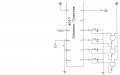
Re-set up circuit with "AND" gates using 2.2K resistors on LEDs.
#1 - #1 LED lights
#2 - #1 & 2 LEDs light
#3 - #1 & 2 & 3 LEDs light
#4 - #1 & 2 & 3 & 4 LEDs light
#5 - All off
---------------------------------
MY GOD ! ! ! ! ! ! ! !
---------------------------------
Replaced 2.2K resistors with 100 ohm resistors
#1 - #1 LED lights
#2 - #2 LED lights (#1 goes out)
#3 - #2 & 3 LEDs light
#4 - #4 LED lights (others go out)
#5 - All off
-----------------------------------
Conclusion =
2.2K resistors indeed accomplished the task !
Red LEDs seemed about the same brightness.
Inquiry =
Please explain how/why you came up with the values of 2.2K ??
--------------------------------
It's a matter of balancing how much current the 4000 series CMOS IC's can source or sink, keeping in mind the current it takes to light the LEDs, along with what voltage is required to operate the logic portion of the circuit.

Even 2.2k Ohms was pushing it. With Vdd=12v, sourcing 4mA will cause the IC's output to drop a volt or two according to the datasheet.

My goal was to make as few changes as possible to enable your circuit to function. The intensity of the LEDs was not a big concern; just that you could tell whether they were on or off.

So, after looking at Motorola's datasheet for the 4017, I decided that 4.5mA was about the most current it could source with a 12v supply without losing (dropping) too much voltage across the IC's internal circuitry. You also have diodes in the output path of the ICs, which will have about a 0.6v drop across them.

I assumed you were using LEDs that had a Vf of 2v.
So, what resistance was required to get the current down below 4.5mA?
Rlimit >= (Vsource - (VfLED+Vfdiode)) / 4.5mA
Rlimit >= (12v - (2v+0.6v)) / 0.0045 A
Rlimit >= 9.4 / 0.0045 = 2,088 Ohms.
The closest standard value of resistance >= 2,088 is 2.2k Ohms.

Then you replaced the 2.2k resistors with 100 Ohm resistors. I would not be surprised to find that those ICs are now fried, as you have subjected them to current far beyond what they were rated for.

Keep this in mind while you're experimenting: very few 4000 series CMOS IC's will survive if you subject them to high load currents. For typical logic circuits, they will last much longer if you keep the load currents below 2mA.
 
Last edited:

SgtWookie

Joined Jul 17, 2007
22,230
Radio Shack LEDs: I suggest that you do not supply them with more than 20mA current. Otherwise, they will have a very short life.

You can make a simple constant current source out of an LM317 regulator and a resistor, connecting the resistor (I'll call it R1) between the OUT pin and the ADJ pin, and taking the current from the ADJ pin. The LM317 will drop roughly 3v across itself when used like this.

The general formula for determining the value of R1 is:
R1 = Vref/DesiredCurrent
where 10mA <= DesiredCurrent <= 1.5A, and Vref is 1.2v to 1.3v, nominally 1.25v.

You can determine the value of Vref for your individual LM317 by connecting a 100 Ohm resistor from OUT to ADJ, grounding ADJ, supplying IN with 3.5v to 5v, and measuring the voltage from ADJ to OUT.

So, if you want a 20mA constant current supply, and let's say you measured 1.27v for Vref:
R1 = 1.27 / 20mA
R1 = 63.5 Ohms
The value of R1 needs to be very close in order to get the current you want.
Here is a very handy page for calculating resistors in series and parallel to get the value you need:
http://www.qsl.net/in3otd/parallr.html
Select R24 for the series by clicking the down-arrow, and then type the resistance value you need into the box, then click the calculate button.

When you're using the LM317 as a constant current source:
1) Turn your breadboad's power off
2) Turn the variable +V down to minimum
3) Connect your LED to test into the breadboard, cathode (short lead) to ground
4) Connect the LM317 between your variable +V (IN terminal) and the LED's anode (ADJ terminal).
5) Connect your volt meter across the LM317 (IN to ADJ).
6) Turn on the breadboard power, and slowly turn up +V until the voltage across the LM317 reads about 3.5v.
7) Measure the voltage across the LED; that is it's Vf @ 20mA.

Radio Shack carbon film resistors are actually pretty good. I have had a couple of their assortments sitting around for a number of years, and they have been pretty stable. They are usually just a small percentage less than they are marked, but occasionally they are slightly above their markings.
 

Thread Starter

Oxbo Rene

Joined Feb 20, 2009
201
Tx's so much Sarge !
You are an incredibly intelligent individual !
I copy/file all your advice .
What this circuit is, is going to be part of a "Scoreboard".
My son is a coach at a high school over there in Orlando.
He has asked me if I could build him a portable scoreboard for his wrestling
team, as, they have none and a good one runs around $1,500.00.
This particular circuit is for the "Period" count (4 periods to a tourney, etc).
Being layed off and getting back interested in electronics, sitting around here , I figured it would be a good project to do.
So, will probably be having more problems I'll be bringing to the forum.
Once again, thanks so much, to everybody........
Oxbo
(See attached pic)
 

Attachments

Bernard

Joined Aug 7, 2008
5,784
Just one more question; at reset,output "0" will be high & not as described; maybe all outputs are shifted up one position from that shown on last drawing, so that "0" is open, "1"goes to LED 1, etc.
 

Thread Starter

Oxbo Rene

Joined Feb 20, 2009
201
I think I know what your getting at Bernard.
I just went out there and cut circuit on,cycled all LEDs to off, then cut power.
Upon power-up, sure enough LED #1 came on.
Appreciate your pointing that out for me sir.
Will make necessary adjustments in the morn, etc.......
Tx Yu,
Oxbo
 

Bernard

Joined Aug 7, 2008
5,784
Either way works fine, leaving "4" blank as is , or "o" blank. 'not too much trouble on startup to key up to # "4" all off to start.
 

SgtWookie

Joined Jul 17, 2007
22,230
I wouldn't use the circuit as-is in a permanent application. 4+mA is a lot to ask from 4000-series CMOS IC's that weren't specifically designed for that kind of current.

Besides, you're going to want to drive more LEDs with it anyway.

One of those ULN2804 or ULN2004 ICs would work well to sink current from the cathodes of multiple LEDs.
 

Thread Starter

Oxbo Rene

Joined Feb 20, 2009
201
I've been thinking about that this morning Sarge.
Figured perhaps the output from the 4017 would go directly into a
ULN2004A and then this device would drive the LEDs.
In this particular application there will only be four lights.
They'll be quite large, possibly not even LEDs, say, 1.5 inch+ across the face of each (if I could locate such ones).
Got my trigger/pulse circuit drawn up and tested on the breadboard.
Had a diode on the output on pin #3 but operation always seemed to miss fire, fire two LEDs at once, not quite sure what was with it. Trouble shot it and when I took diode out of circuit, everything worked real well.
Please examine (attached) for correctness, etc.......
Output pulse set at 1/10th sec.
This thing is going to be a BOSS ! (see LED sizes=attached)
And, what about a "colon", just turn one up? I think I need to fabricate one as I could'nt find any on the net. But, that discussion is for a new thread, etc.......
Oxbo
 

Attachments

Last edited:

Bernard

Joined Aug 7, 2008
5,784
This is what it might look like. If you want to keep C1, make it smaller than C2, R3 no purpose, already have R2 in series with SW."AND" gate [ non invert amp. ] no longer needed ?? 4 diode drops still should leave plenty of drive for ULN2004. All comments subject to review.
Same problem every month with new file, and I forget how to correct every month, so 'llsave what I have.
 

thatoneguy

Joined Feb 19, 2009
6,359
A "Colon" is often made with 2 LEDs. With that HUGE clock, you may want to go with 10mm LEDs ( ≈0.4" diameter ), it appears the decimal points are 1/2" diameter from the reference ruler.

With digits that big, it would be cool to put in a Granfather Clock case, and have the Colon blink with the pendulum. Keep the phase of moon dial behind the time display. Tinted acrylic over digits/leds of course.

Another use for this would be to paint a bunch of empty paper towel holders red, tape them together, stick a bunch of random curly wires into it ala movie bomb, and have it light up a 5 second countdown in your boat when it is bumped.
 

Thread Starter

Oxbo Rene

Joined Feb 20, 2009
201
This is what it might look like. If you want to keep C1, make it smaller than C2, R3 no purpose, already have R2 in series with SW."AND" gate [ non invert amp. ] no longer needed ?? 4 diode drops still should leave plenty of drive for ULN2004. All comments subject to review.
Same problem every month with new file, and I forget how to correct every month, so 'llsave what I have.
See "IC Timer Cookbook", pg # 113........
According to that,
Quote->
"Prior to actuation of SW-1, C1 is charged to V+ through R1. Depressing SW 1 discharges C1 rapidly through R3, creating a short negative spike. Any sporadic effects of switch bounce that may occur when SW-1 is depressed are removed by the integrating action of R1 and C1. The resultant clean negative spike is then passed through C2 to the 555 as a trigger pulse..
Upon release of SW-1, C1 recharges to V+ and the circuit awaits the next switch actuation".
There ! Now, See ! ! ! :):)

And, which "AND" gate do you say I don't need ???
 

Thread Starter

Oxbo Rene

Joined Feb 20, 2009
201
A "Colon" is often made with 2 LEDs. With that HUGE clock, you may want to go with 10mm LEDs ( ≈0.4" diameter ), it appears the decimal points are 1/2" diameter from the reference ruler.

With digits that big, it would be cool to put in a Granfather Clock case, and have the Colon blink with the pendulum. Keep the phase of moon dial behind the time display. Tinted acrylic over digits/leds of course.

Another use for this would be to paint a bunch of empty paper towel holders red, tape them together, stick a bunch of random curly wires into it ala movie bomb, and have it light up a 5 second countdown in your boat when it is bumped.
You been drinkin ???? :rolleyes::rolleyes:
 

SgtWookie

Joined Jul 17, 2007
22,230
So, why not use banks of LEDs?

If you were powering LEDs using say, 12v, you know that the ULN2xxx series can sink up to 500mA per output, right? But for long life, let's de-rate it to 200mA.

Vce will be roughly 1v with a 200mA current, which gets subtracted from the 12v.

Let's say you're using some LEDs that had a Vf of 2.3v@20mA
11v / 2.3v = 4.78... - take the integer value, which is 4.
4 x 2.3v = 9.2v
So the limiter resistor would then be (11-9.2)/20mA = 1.8/.02 = 90; closest standard value is 91 Ohms.

You could have 10 strings of 4 LEDs (40 total) being driven from a single ULN2xxx driver output. You could use two outputs for a total of 80 LEDs for each 4017 output, and the driver would be running at 2/5 capacity.
 

Thread Starter

Oxbo Rene

Joined Feb 20, 2009
201
Back now, had to run, etc......
Naw, don't think I'd enjoy installing 80 LEDs, drilling holes, mounting them, wiring them, nope, don't need that.
Am pretty well on top of things now.
Appreciate everything, will be back when next problem arises.
Oxbo
 

Bernard

Joined Aug 7, 2008
5,784
Back to page 48, pic. R3-C1 time constant is 10μs, not long enough to block out SW bounce, ave 10-20 ms. R1-C2 ,10 ms & .1 s output do the debouncing. Or as Forrest Mims III did it: tie P2[555] to + with resistor, attach SW from P2 to ground to make a bounce free pulse gen.
Same pic. ; if using the ULN 2004, the 3 "AND" gates not needed, eliminate +12v connection, connect each input to ea. out,; re-drawn it looks better. Just a cascaded diode OR gate feeding the driver. Sorry that I can't get attachment to work, guess it's April 1.
 

Thread Starter

Oxbo Rene

Joined Feb 20, 2009
201
Well, that looks great but, how is it going to give me--->
#1 = 1 led lit
#2 = 2 leds lit
#3 = 3 leds lit
#4 = 4 leds lit
#5 = all off
Please explain the process for me ????
I see the diodes, are the output pins of the 4017 at ground when off, etc?
 
Top