LED sequencing problem

Thread Starter

Oxbo Rene

Joined Feb 20, 2009
201
Good afternoon.
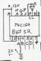
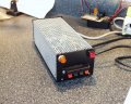
Since having been able to move on after the breadboard repair, I have finished the little $6.00 power supply, finding a nice little chassis, it came out pretty good.
+12V@2A/+5V@3A/-5V@.35A, not bad at all. Need to get some white dry transfer stickers to put the appropriate labels on etc.
----------------------------------------------
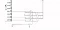
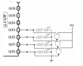
OK, now I'm working on a particular circuit where I want to push a button and a LED will light up, push the button again and two LEDS light, push the button again, three LEDS light,
once more and four LEDS, then, a final push and all LEDS are off.
Have been playing around with a 4017 and can get the LEDS to alternately come on and everything goes off with reset tied back to pin#1, leaving pin#10 blank for that.
And thought I had a solution for making them act as I wanted (see "AND" gates solution attached), however, seems they load down and don't want to co-operate, etc.
Anyone got any suggestions ?
Have a nice day,
Oxbo
 

Attachments

Mike2545

Joined Mar 26, 2009
116
Whoops! SgtWookie, We cross posted. Well I didn't catch the outputs connected together without the diodes, still would like to know what he is powering it with...

Mike2545
 

SgtWookie

Joined Jul 17, 2007
22,230
Howdy,
You have some illegal conditions going on there... you have multiple outputs connected together for one, and you're trying to use a single resistor for limiting the current through one and all of the LEDs.

You can't connect the outputs of standard logic gates together; they will "fight" each other. (There are some exceptions to this, as in "open collector" TTL logic gates).

See the attached. I've added a bunch of itty bitty diodes to your schematic so that the outputs won't fight each other, and resistors for your LEDs.


[eta]
Added output diode on the bottom AND gate!
 

Attachments

Last edited:

SgtWookie

Joined Jul 17, 2007
22,230
Whoops! SgtWookie, We cross posted. Well I didn't catch the outputs connected together without the diodes, still would like to know what he is powering it with...
Hi Mike,
Yeah, I posted, then I deleted because I realized I'd put in a few too many diodes! Had to re-work it really quick.

Oxbo's using a handy-dandy super-duper breadboard that has a built-in fixed and variable power supply; 5v fixed @1A, and +/-15v adjustable @500mA. I think it's this one:
http://www.mpja.com/prodinfo.asp?number=17710+TE
He had a bit of trouble with it a week or so ago after shorting the positive supply, but it got sorted out.
 

Mike2545

Joined Mar 26, 2009
116
1A you say? that is plenty big enough for this circuit. I had thought he may be overtaxing his supply as well.

Lets see if when he makes those changes, if it doesn't fix him right up :)
 

SgtWookie

Joined Jul 17, 2007
22,230
Well, I still have my doubts; it's quite a load to drive LEDs AND logic for the old 4000 series CMOS. However, the diodes at least will relieve the output contention problem.
 

Bernard

Joined Aug 7, 2008
5,784
Is this correct, one push,# one LED lights, 2 push #1 &#2 light; 3 push.#1. #2 & #3 light; 4 push , #1, #2 #3, & #4 light; 5th push all extenguish ?? This ckt should do it. Load the shift register with 1's one at a time, on 5 th, out E is inverted and applied to clear. outputs,ABCD, connected to NOR gates. Lots of options for driving LED's, lightly loaded directly from gates; invert gate outputs and drive fet or transistors. Pin 8 is clock, needs rising edge to trigger, tie to ground with 10k and apply +V with sw, best if debounced.
 

Attachments

Bernard

Joined Aug 7, 2008
5,784
Cought gilding the lilly again: we dont need the gaiting, just the inverter for clear, drive the LEDs & resistors directly from SR outputs, or add drivers if brighter light wanted. Output should source or sink 8mA.
 

Thread Starter

Oxbo Rene

Joined Feb 20, 2009
201
I have messed with the setup Sarge has offered, and for some reason, it just don't work right,
I get the first LED to light, second push of the button = two LEDs lit ! (that says right there that it'll work)
Third push of the button=third LED lights, but, first two go off.
Fourth push of the button=4th led lights by itself.
So, seems like it should work, maybe I'm getting wires crossed, but, have rebuilt it over and over all morning.
One problem I have is, I only have a chip of NAND gates, so have to run their outputs through inverters, then through the diodes, lots of wires everywhere.
Am pretty sure it'll work, just got to find the bug there at third LED, maybe that NAND gate is bad, got to go look closer, etc.
Bernard, could you please explain your last post where you say I don't need gates, etc.
I don't ave any NOR gates handy to try your setup.
Tx's
Oxbo
 

Bernard

Joined Aug 7, 2008
5,784
I've trimmed off the extraneous gates, now just the 74C164, SR & an inverter, IC or transistor, with LED driver of your choice. Not as simple, need more parts, but a pair of, maybe 3 dual FFs 4013 could be used to replace 74C164 if un available. " dont think 4017 will work without adding some memory like a 4043M ,R/S latch; might not be a bad 2nd choice as you already heve a 4017 or 4022.
 

Attachments

Thread Starter

Oxbo Rene

Joined Feb 20, 2009
201
Tx's Bernard;
Seems like as common an application as this is, there ought to be a LED chip out there that would accomplish this.
I haven't messed with it any more as my "tilt" switches for my boat alarm came in (mercury).
Am going to mount one on an arm (4" long) to the left and the other on an arm (4" long) to the right, have btms bolted one on top of the other to back plate where they can be raised/lowered by adj screw on other end, thereby being able to fine adj their sensitivity. Whole back plate must be able to be adj for level (in case boat has one wheel in a hole/not quite level, etc, etc), Adj back plate first, then tilt switches (will have LEDs to indicate when either switch is making contact, adj back plate till leds go out).. Then once all that is squared away, activate, etc, etc.
So, will have to get back to this (LED) project after finishing boat alarm, etc.
Tx's everybody......
Oxbo
 

Thread Starter

Oxbo Rene

Joined Feb 20, 2009
201
I appreciate it Mike.
However, that stuff is all Greek to me.
I tried to get into Basic programing years ago but grew quite bored and disillusioned with it.
I am impressed with these programmable chips, and really feel I need to learn em, but, when I see that program code stuff, it just turns me off, makes no sense to me.
I can do HTML a little bit, but that makes at least a little bit of sense.
Anyway, this is the first I've heard of the "Stamp" chip, and how in the world does one program it, etc ?
That means I got to buy a book, spend hours studying, probably buying lots of extra stuff, experimenting, Oooh Man !
I'm sure it's as easy as pie to ya'll, I just don't know where to start, and sure don't want to waste a lot of time.
Feel free to persuade me into learning it, I'm open minded, as long as I can see a ight at the end of the tunnel.......
 

SgtWookie

Joined Jul 17, 2007
22,230
Well Oxbo, why don't we just see what's going on with what you have right now? ;)

No sense in spending money on stuff when you have some stuff on hand that should do the trick.

Basic Stamps are made by Parallax, Inc. In comparison with most other microcontrollers on the market, they're expen$ive - and relatively slow. They are programmable with a version of the Basic language, which makes them somewhat "user friendly", so they're popular with schools - if the school can afford the kits. A "Board of Education" starter kit runs about $130, which isn't exactly chicken feed in the current economy. Microchip has a PICkit 2 Debug Express kit that runs about $50, which although has a slower internal clock speed, can effectively run faster than a typical BS1 or BS2 Stamp. The microcontrollers are much less expensive, too - $0.50 to $5 compared to Parallax' $34 to $80 or so uC's. There are quite a few other microcontroller manufacturers; Atmel seems to be popular lately - but unless you're interested, I'm just typing into a void.

Back to your situation:
You get the bottom LED lit OK.
(press button)
You get the bottom two LEDs lit OK.
(press button)
The bottom two LEDs turn off, and you get the 3rd LED lit.
Right?
If so, then the 2nd AND gate (that you've made from a 4093 NAND and an inverter) is having a problem.

What is your Vcc/Vdd? (supply voltage)
What voltages do you measure on each input to that 4093 NAND gate, and what voltage is on the output of that NAND gate?

Did you remember to wire ALL UNUSED INPUTS of the 4093 and the inverter to either Vcc/Vdd or ground? If you didn't, that will cause big problems.

With CMOS logic IC's, it is OK to leave the OUTPUTS not connected to anything. However, if you leave ANY INPUTS unconnected, the IC can start oscillating at random frequencies, and it will be very difficult to figure out what's wrong.
 

Thread Starter

Oxbo Rene

Joined Feb 20, 2009
201
Gimmie some time Sarge........
Will try it again tomorrow......
Sure wish Radio Shack had the stuff like they used to, their stock gets smaller and smaller every time I go down there.
Oh yeah, got that little chassis for the $6.00 pwr supply down at Skycraft the other day.
Here's those exact same relays I had to pay $3.00 ea at Skycraft for....
http://www.goldmine-elec-products.com/prodinfo.asp?number=G1934&variation=
They're not the same "surplus" place they used to be for sure.
I believe they want $1.50 ea for 555's, a bit high.
But, I still get dizzy walking around in the place looking at all the stuff.
OK, good night......
Oxbo
 

Mike2545

Joined Mar 26, 2009
116
I appreciate it Mike.
However, that stuff is all Greek to me.
I tried to get into Basic programing years ago but grew quite bored and disillusioned with it.
I am impressed with these programmable chips, and really feel I need to learn em, but, when I see that program code stuff, it just turns me off, makes no sense to me.
I can do HTML a little bit, but that makes at least a little bit of sense.
Anyway, this is the first I've heard of the "Stamp" chip, and how in the world does one program it, etc ?
That means I got to buy a book, spend hours studying, probably buying lots of extra stuff, experimenting, Oooh Man !
I'm sure it's as easy as pie to ya'll, I just don't know where to start, and sure don't want to waste a lot of time.
Feel free to persuade me into learning it, I'm open minded, as long as I can see a ight at the end of the tunnel.......
I agree that the Stamps are slower than PIC or any other Micro controller out there, however for this type of application they are great.
I will also agree that they are more money than others out there ($30.00 for a BS1) but you get great support on their website.
As far as programming, free software and a serial cable, you can do it without a development board but for the BS1 you will need the serial adapter ($4.99).

The syntax is relatively straight forward, pick up one book and you will be hooked. If you stay with the Stamps, great, maybe you will move on to PIC or AVR. I just ordered a PIC Junebug, to play in that arena.

You can cut and paste the code I gave you directly in the Basic Stamp editor (Free download), hook up a BS1 with the leds (and resistors + pushbutton) and you are ready to go.

Mike
 

thatoneguy

Joined Feb 19, 2009
6,359
For Microcontroller stuff, I started a new thread HERE

On topic, it looks like Ox has the right design from Sarge, not sure why the 1-2 transition keeps the '1', while the 3-4 transition clears all, though. They should act the same way or not at all from the schematic.
 
Top