 Facebook
 Google
 GitHub
 Linkedin
Hi guys,
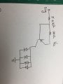
Wanted your opinion about a simple circuit I'm thinking of MODing. Basically its one of those LED lights on a bicycle. When you turn it on and off and on again it changes the brightness. Its controlled by a unidentifiable IC RL001.
Anyway I want to change the button to a latching type button and when its on the LEDs are at full brightness. Take out the control IC altogether.
I've attached the original circuit and the two options I was thinking of
Option A:
When I place the switch at the position and when its in the off position the LEDs are completely off (obviously). But whats interesting to me is that if I touch the open end near the 1M resistor the LEDS come on. If I touch it with the DMM probe it lights as well. I'm wondering why that is? Its not a huge issue but my reservation is that if the light is assembled and if there is any sort of static it would turn the LEDs slightly on which would drain the battery.
Option B:
This is the simplest design I can think of. But wanted to ask if there would be any issues by placing the switch there. Do I need capacitors across the switch?
Also I'm thinking of changing the 5.6K resistor to a 10K resistor by doing so low current is drawn from the supply and I'm pretty happy with the illumination level.
Lastly I wanted to ask with this circuit how does the transistor used. Is it used for the purpose of a constant current source? Or is the only reason because the light was designed to illuminate at different brightness.
While experimenting I noticed that I can take down the input voltage(supposed to be 6V) all the way down to 3ish volts without seeing any difference in the illumination level.
Thanks in advance.
P.S: The transistor is 8550
Attachments
-
 663.3 KB Views: 17
 -
 635.1 KB Views: 16
 -
 688.7 KB Views: 16


