LED light control

Thread Starter

Poppa D

Joined Aug 30, 2020
36
Grow Light from Amazon has these available settings:
Time on 3, 6, or 12 hours
Color RED, BLUE or RED & BLUE
Intensity 4 levels brightest to off

All seem to work, correct leds come on for times, colors change, intensity decreases, but if you go one click beyond max/min for any switch it shuts off and you have to start all over. Does not matter what time setting you choose it will burn for 4 to 15 minutes and turn off. None of the settings are saved/stored so you have to start all over again each time it is powered on.

GOAL is to have them stay on constantly (on/off controlled by external timer), red & blue lights on (default is red only when powered on), and intensity on highest setting (this is default when powered on)

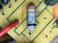
New to LEDS and would like suggestions on how to accomplish GOAL by soldering jumpers in this control module if possible. BIG question is why LOW DC values (.07 and .11) at terminals that go to lights when set to desired parameters? Attached pdfs show light and control module with DC voltage readings.
Any help would be appreciated,
Poppa D
 

Attachments

AnalogKid

Joined Aug 1, 2013
12,130
Photos of the power source? If it is a wall wart or inline supply, please post a *clear* close up photo of the label.

The chip on the back side probably is a microcontroller (uC), like a PIC. The two LED outputs O1 and O2 are switched to GND (ok, close to GND) by the two outboard transistors Q1 and Q2. It is interesting that the power source sags so much under load.

The uC is causing dimming by driving the LEDs with a square wave; they are switching on and off very rapidly. As the ratio of on time to off time changes, they appear dimmer. This is called pulse-width modulation (PWM).

There is no way to reprogram the uC to do what you want. For example, the fact that the system powers up in red-only mode is built into the uC's firmware. That board can be replaced by something optimized for your specific needs, either with a similar uC, something larger like an Arduino, or with all discrete logic parts.

ak
 

AlbertHall

Joined Jun 4, 2014
12,625
GOAL is to have them stay on constantly (on/off controlled by external timer), red & blue lights on (default is red only when powered on), and intensity on highest setting (this is default when powered on)
Do I understand correctly that you want red and blue on at full brightness whenever power is switched on, and to have no control over them from the buttons on the board?
 

Thread Starter

Poppa D

Joined Aug 30, 2020
36
Its a wall wart see attached pic. The only function that would be nice (but not necessary) is the color functions. This is an attempt to use this light on outside of old aquarium that had small fluorescent tubes that ballast have burned out. The timer used with old lights worked great lights would be on for 8 to 10 hours a day and off the rest of the time.

Based on Kid's post can I just jumper O1 and O2 and then jumper to GND? Thought about doing this, but was not sure if it would ruin LEDs. This would mean entire board could be removed and this would become a junction box.

Thanks for quick responses was not expecting that,
Poppa D

Switches are 1=power, 2=timer, 3=color and 4=intensity
 

Attachments

Last edited:

AlbertHall

Joined Jun 4, 2014
12,625
Based on Kid's post can I just jumper O1 and O2 and then jumper to GND? Thought about doing this, but was not sure if it would ruin LEDs. This would mean entire board could be removed and this would become a junction box.
Yes, you can do that, and ditch the board.

The only function that would be nice (but not necessary) is the color functions.
You could use ordinary switches to control the two LED colours. When the board isn't inside the box, maybe there would be room to fit the switches inside the box.
 

AnalogKid

Joined Aug 1, 2013
12,130
That is a simple constant-voltage power supply, so current limiting must be built into the lights.

With no dimming, it sounds like the pc board can be eliminated, and replaced with two toggle switches (red and blue) and a lamp timer from Wallmart.

ak
 

Thread Starter

Poppa D

Joined Aug 30, 2020
36
Thanks Mr. Hall & Mr. Kid, may try utilizing existing switches for color selection? Isolate switch 3 some how and solder new leads to LEDs? Plenty to play with will update once I get it rewired and working.
 

Thread Starter

Poppa D

Joined Aug 30, 2020
36
Removed circuit board, installed simple slide switch to turn red lights on (JB WELD) blue lights always on, rewired and plugged it in, everything seemed fine. Reinstalled on aquarium and plugged in to timer, came back in 10 minutes and lights were flickering on and off 1 to 3 second intervals, thought lose solder connection. Reached to unplug HDMI from power supply and power supply transformer (wall wart) was HOT to the touch. Found another transformer, reconnected lights and they worked all day today and turned off after 12 hours.

Lesson learned: If a company makes thousands of units and no major bad reviews then the circuit boards are probably not going to be bad, but wall wart may be going bad and should be checked before trying to fix something that’s not broken.
Thanks for all the help, learned quite a bit from you two and now have new aquarium lights.

Knowledge in a wonderful thing, if you don't let it go to your head!
Poppa D
 

MisterBill2

Joined Jan 23, 2018
27,517
I expect the existing switches will be momentary only so they won't do for the new system.
TRy this experiment: Press and hold a button and see what happens. That will let you know what the result of soldering in a juper will do, and it will be much simpler. AND NO, you can not reprogram the controller. and even if you could, no hint as to what to program in. It is not an arduino.
 

Tonyr1084

Joined Sep 24, 2015
9,744
Overheated wall wart? Probably drawing more current than it was capable of. Bigger wall wart (higher amperage rating) needed.

If the LED strings are drawing 700 mA and your wall wart is rated for 500 mA then it's either going to get very hot or immediately shut down (over current protection internally).
 

Thread Starter

Poppa D

Joined Aug 30, 2020
36
Tony1084 got me wondering so took wall wart apart and found capacitor blown and resistor cracked and flaking, had capacitor but am a little puzzled by this resistor, 5 band: orange, orange, gold, gold, black, none of the 5 band calculators allow a gold for the third color so what size is this?
 

Attachments

MisterBill2

Joined Jan 23, 2018
27,517
That may actually be an inductor, since in the photo it looks like it is installed in the place where an inductor or transformer would have been. So it might be part of the conducted noise filter.Look at the underside of the PCB and see what sort of connections go to the other two holes in the outline shown on the top of the board.
 

Tonyr1084

Joined Sep 24, 2015
9,744
The resistor kind of looks like an inductor just as @MisterBill2 suggests. Check it for continuity. Even flaked, it may still be functional. I'm repairing a computer mother board that had quite a few swollen electrolytic capacitors. You said you found a "Blown" cap. I didn't notice any caps that appeared blown in your picture. Were you only shooting the resistor thingie?
 

MisterBill2

Joined Jan 23, 2018
27,517
After a much closer examination of the one picture I see turns of wire. So the device is either an inductor with not very many turns or a low value resistor. Gold and silver bands are used for multipliers of 1/10 and 1/100, so it could be a 5% tolerance 0.33 ohm or 0.033 ohm resistors.
 

Thread Starter

Poppa D

Joined Aug 30, 2020
36
Bad cap had been removed and no continuity on inductor, still not sure what it is, inductor color code for 5 bands says 1st ban will always be silver (for Mil ID) which is not the case for this component. Wall Wart.jpg
 

MisterBill2

Joined Jan 23, 2018
27,517
Based on the red lines equating to connections on the circuit side, the device was both an inrush limiting resistor and a fuse, which has pailed and protected other parts.yes, 0.33 ohms is a reasonable value for it.
 

Thread Starter

Poppa D

Joined Aug 30, 2020
36
Diodes all check okay will find resistor and post results Thanks for all the input
"sghioto, post:
I see a .33 ohm 5% wire wound resistor rated at 3 watts." Care to share how you determined wattage value?

Does this resistor fall under the following:
Color Code Exceptions
5 Band Resistor with a 4th Band of Gold or Silver
Five band resistors with a fourth band of silver or gold form an exception, and are utilized on specific or older resistors. The first two bands represent the significant digits, the third band is a multiplication factor, the fourth band is for tolerance and the fifth band is for the temperature coefficient (ppm/K).
 
Top