LED Flasher workaround?

Thread Starter

seanstevens

Joined Sep 22, 2009
323
Hi All,
I have an LED flasher design that uses 9 LEDs and works well, to improve its efficiency and address the issue, which is the delayed startup flash as it takes about 5 seconds for the first flash.
The device works from 16V-24VDC, with Vf LED of 10.5V each. So I am using a voltage step-up circuit that reaches around 130VDC. All this works well and I don’t really want to change much of it.
The delayed start-up flash is obviously do to the fact that it takes a few seconds to raise the voltage to the minimum voltage to light up the LEDs. It is taking this time on purpose to reduce the operating current, I can make it faster at the cost of extra current, not an option. A work around I thought, is to bypass a number of LEDs at the start until the voltage gets where it needs to get to light up all of them and then stop bypassing them.

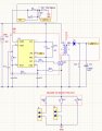
So, I thought to use a P-MOSFET to basically short out a number of the LEDs and when the voltage gets to a certain level, the MOSFET would switch off and no longer bypass the LEDs, and normal operation would then resume. So ideally, at the start, maybe 3 LEDs would flash, and once the voltage has reached say 110V or thereabouts, the bypass is removed. So I was wondering if this is doable in a simple way as described. I don’t normally use LTspice, so no expert by miles, but I have attached the sim to give you a simplified circuit

D10 is to drop the input voltage to within the limits of the (random P-MOSFET). R1 & R2 create a voltage divider for the switching point, and R3 is a limiting resistor for the active LEDs at the start.

Would appreciate your inputs and suggestions.
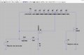
 

Attachments

MisterBill2

Joined Jan 23, 2018
27,402
I think that will not speed the startup and also think it is asking for trouble.
WORSE, I can not open your simulator .asc file to see the circuit.
And understand that in your simulator parts do not overheat and burn up. BUT in the real world they do.
 

sghioto

Joined Dec 31, 2017
8,634
If you bypass or short out a number of LEDs that will increase the current on startup.
Seems to me that the average current would be the same whether its a slow or fast startup.
Why not disconnect all the LEDs until the voltage has risen above say 110 volts?
 

Thread Starter

seanstevens

Joined Sep 22, 2009
323
Thanks for your responses. I dont understand why you cant open the .asc file. I will re attach again as well ass a screen capture just in case.
@MisterBill2 I know it won't speed up the start-up. What I am trying to do is flash at least a few LEDs before the 'reservoir cap' gets to its full voltage of 130V so that I can flash all LEDs. This prevents the user from thinking something is wrong and prevents the appearance that the first flash takes 4-5 seconds after the switch-on. Also, the average current is irrelevant at this point. The main point here is to have a flash within the first couple of seconds.

@sghioto The LED voltage rises from 0 to 130V in 4-5 seconds, and I plan to bypass, say during 2-3 seconds, i.e. very early and therefore much lower voltage and lower current, also looking to place a resistor in series for the bypass. As mentioned above, the whole purpose of the exercise is to prevent the impression of no flash for 4-5 seconds after switch-on. I don't mind a dimmer than usual flash output in the first couple of seconds, but it's got to flash.

@AnalogKid .asc and image attached. LEDs are just random LEDs in the circuit.
 

Attachments

MisterBill2

Joined Jan 23, 2018
27,402
I see no capacitor in the posted circuit! As for not being able to ope the " .asc" circuit, I do not have that simulator, which is the only thing that will open that circuit file.
Probably the time constant to charge some capacitor is the cause of the 5 second delay, a faster charge or a smaller capacitance will be the solution to reduce the delay.
 

schmitt trigger

Joined Jul 12, 2010
2,062
Have you actually measured the voltage’s rise time or you are assuming that is the issue?

It could be that the circuit that actually drives the flashing is taking longer during the first flash than the steady state flashing period. Certainly a 555-based timing circuit would have that behavior.
 

AnalogKid

Joined Aug 1, 2013
12,102
For the FET shown in the M1 schematic, the datasheet max Vgs is +/-8 V. You have a 30 v zener diode between the gate and source, so that's a problem. Even if that is a place-holder part, most "normal" FETs have a max Vgs of +/-20 V, so the drive circuit still has a problem. When V1 is at 130 V, the current through R1 and R2 will be 20 mA. That works out to a Vgs of 109.6 V.. Thus, the M1 drive circuit still needs work.

Begin with a 12 V zener diode clamp between the gate and source (just the diode, no series resistor), and work outward from there.

And, there is no current-limiting resistor R3.

ak
 
Last edited:

Thread Starter

seanstevens

Joined Sep 22, 2009
323
OK, gents, maybe I didnt make myself clear in the previous posts. The circuit I provided is a very basic if you like block diagram, not the entire circuit for the design. It was done quickly to just try the bypass mosfet section. Certainly, the flash MOSFET M2 is just a mosfet, so please ignore that. Also please dont concern yourselves with the step up and charging the cap and its timing.
My question here is only about the idea of bypassing 6 of the 9 LEDs with the idea that I described in my previous posts. So forget the right side of the circuit (block), I just want to know if that idea of using a mosfet in this situation would be possible to do what I want to do.
@MisterBill2 I do not normally use that sim either, however, it is free and everyone here seems to use it, so I thought it might be useful if anyone wanted to try it. I am fully aware that the cap charge time is due to the time constant. Changing that is not an option in this case, as it will increase the overall current consumption of the unit, I am perfectly happy with it. My question is specific to the use of the mosfet. In fact, if you are more comfortable, just assume the cathode is connected to the negative - but my question re mosfet bypassing the first 6 LEDs remains.
@schmitt trigger Yes, I have a prototype that works great, but as mentioned it has a start-up flash delay which is preferred to higher current, hence the search to find a workaround to just make 3 LEDs flash for the first couple of seconds whilst the reservoir is charging to the nominal voltage.
Sorry, dont meant to be vague, but as I say, my question is specific to the mosfet and whether it is possible to use a mosfet in this LED configuration and when the gate voltage reaches a certain level, it will open the bypass.
 

sghioto

Joined Dec 31, 2017
8,634
@sghioto The LED voltage rises from 0 to 130V in 4-5 seconds, and I plan to bypass, say during 2-3 seconds, i.e. very early and therefore much lower voltage and lower current, also looking to place a resistor in series for the bypass.
If there are only 3 LEDs active during the bypass a current limiter will be required as the voltage rises towards 130 volts.
The Vf of the LED is 10.5 volts then at 31.5 volts the 3 LEDs should flash is this correct?
How much current does the full LED string use at 130 volts?
What is drawing this current on the startup, is it mainly the LED string or the boost converter?
If the boost converter has no load meaning the LEDs are not connected what is the current draw at startup?
 
Last edited:

MisterBill2

Joined Jan 23, 2018
27,402
I think that with only 3 LEDs active at the start that very rapidly there would be NO LEDs active.

and I am not able to offer any advice about the actual circuit because that portion has not been posted. To get any reasonable advice about that circuit we will need to see it. IF the TS does not choose to show us the present driver circuit there is no hope for useful advice.
 

Thread Starter

seanstevens

Joined Sep 22, 2009
323
@sghioto Yes, that's R3 as a symbolic current limiter. You are also correct about the Vf of the LEDs; at 31.5V, the 3 LEDs should flash. The full string consumes about 2.6A peak on flash at 1Hz, with a pulsewidth of 200mS.
The current consumption at the start-up is the regulator and a boost converter to raise the voltage and store it in a 3300uF charge cap to a level where the LEDs have enough voltage to flash. I am not in a position to capture the voltage rise on a scope, but suffice to say, with full string, the first flash appears at around 4 seconds after switch-on. So voltage rises across the reservoir charge cap from 0 to 130V in over 4 seconds. The idea is to make the 3 LEDs flash twice before the voltage is at full swing.
The boost converter is feeding the 3300uF cap, thats its load. See attached part diagram of the boost converter and its storage cap, if you imagine the cap replaces V1 in my previous sim diagram, then you should kind of get the picture of whats going on. The M2 mosfet is the switch to turn on the LED string or the 3 LEDs which have not been bypassed.
Thank you for your input so far.

@MisterBill2, as I have pointed out several times above, I am not looking for advice on the entire design or the boost converter, nor the health of the LEDs. I was asking specifically about the use of M1 mosfet as a bypass switch and whether it would actually work as a switch in this configuration. I could just knock it up on a breadboard and try it, it would be quicker, but I value the input of much more knowledgeable people, such as yourself here on this forum, so I thought I would ask. If the information I have provided here vs my specific question isnt enough for you to impart with an opinion, then thats fine too.
 

Attachments

MisterBill2

Joined Jan 23, 2018
27,402
@sghioto Yes, that's R3 as a symbolic current limiter. You are also correct about the Vf of the LEDs; at 31.5V, the 3 LEDs should flash. The full string consumes about 2.6A peak on flash at 1Hz, with a pulsewidth of 200mS.
The current consumption at the start-up is the regulator and a boost converter to raise the voltage and store it in a 3300uF charge cap to a level where the LEDs have enough voltage to flash. I am not in a position to capture the voltage rise on a scope, but suffice to say, with full string, the first flash appears at around 4 seconds after switch-on. So voltage rises across the reservoir charge cap from 0 to 130V in over 4 seconds. The idea is to make the 3 LEDs flash twice before the voltage is at full swing.
The boost converter is feeding the 3300uF cap, thats its load. See attached part diagram of the boost converter and its storage cap, if you imagine the cap replaces V1 in my previous sim diagram, then you should kind of get the picture of whats going on. The M2 mosfet is the switch to turn on the LED string or the 3 LEDs which have not been bypassed.
Thank you for your input so far.

@MisterBill2, as I have pointed out several times above, I am not looking for advice on the entire design or the boost converter, nor the health of the LEDs. I was asking specifically about the use of M1 mosfet as a bypass switch and whether it would actually work as a switch in this configuration. I could just knock it up on a breadboard and try it, it would be quicker, but I value the input of much more knowledgeable people, such as yourself here on this forum, so I thought I would ask. If the information I have provided here vs my specific question isnt enough for you to impart with an opinion, then thats fine too.
In many instances, including this posting, the whole circuit is a system, and so to provide an answer requires seeing the whole system.
In this instance you have already selected a scheme that I would not advise, and asked for verification that it would work as intended. And I already responded that I did not think it would. Upon seeing the whole circuit, I do see another option that was not obvious with only seeing the proposed idea.
I am guessing that the delay to the start of flashing is the time needed to charge that large 3300 MFD capacitor, and so one fix would be to initially only charge a much smaller capacitor, while the main capacitor would charge at a lower current. That scheme would not require any precise timing of the bypass or the risk of damaging the three capacitors.
 

BobTPH

Joined Jun 5, 2013
11,496
Boosting 16-24V up to 130 is not likely to be effcient. If the LEDs need 10.5V, a buck converter to that voltage would likely be more efficient and not have the startup issue you are trying to fix.

The only reason I can think of to put them all in series is to guarantee the same current in all of them. Is that a primary consideration?
 

AnalogKid

Joined Aug 1, 2013
12,102
Agree. This does not appear to be a battery-powered system, so efficiency might not be a big concern. While 9 parallel LEDs would mean 9 current limiters, these could be selected for minimal extra power loss. The trade-offs would be 9x higher flasher switch current, but is instant-on.

ak
 

crutschow

Joined Mar 14, 2008
38,449
Here's your circuit modified, if you still want to use it:
I added a 100V Zener and a BJT to get a sharp turn-off for the MOSFET.
I didn't have models for 10V LEDs so I used 10V Zeners to emulate their drop.
I also added R3 and R5 for current limiting.

(Those who don't like simulators, please avert your eyes :rolleyes:.)

1748006464225.png
 

sghioto

Joined Dec 31, 2017
8,634
Here's your circuit modified, if you still want to use it:
I don't see how that is going to work with the values of R3 and R5.
The TS said the current draw is 2.6 amps peak for the full string, I'm assuming at 130Vdc meaning each LED draws 2.6 amps.
Another thing is the numbers for the LEDs are not adding up.
The TS said the LED Vf is 10.5V but 9 LEDs in series = 94.5 volts. At 130 volts that would be 14.44 volts, so what gives here?
IMHO I think this would be a better way to go about it.

1748014515955.png
 
Last edited:
Top