LED Flasher Help

Thread Starter

liamstears

Joined Jan 31, 2013
31
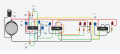
I am trying to make a circuit to flash LED's in a specific pattern, I have a fully working design but it needs to be as small as possible and use as little components as possible so need help in redesigning and making it smaller. I am no genius and most of this has come from what I've found online and some help from chatGPT.

Requirements are that is must be as small as possible, it must run on a 3v battery, lowest consumption possible ideally.

I have attached the schematic that I have that works as intended and here is a youtube link that shows the intended LED pattern:
https://youtube.com/shorts/HyoZw_Ab_Zc?si=aCvCJdoCXnb9PaJ8

Can anyone help me simplify this?
 

Attachments

Thread Starter

liamstears

Joined Jan 31, 2013
31
A single 8-pin microcontroller can replace the three chips in your design. It needs only a small capacitors and the LEDs and their resistors to complete the circuit.
That sounds amazing but I have no technical knowledge to achieve that without help, are you able to elaborate with a wiring diagram? Would I need to program it or is there an off the shelf chip that can do this? TIA
 

BobTPH

Joined Jun 5, 2013
11,463
The circuit is simple, but you would need to program it. That would take a while if you have no prior experience.
 

Thread Starter

liamstears

Joined Jan 31, 2013
31
The circuit is simple, but you would need to program it. That would take a while if you have no prior experience.
Yeh I can do the basics but that's about it, I could easily program a chip with a program that's prebuilt but writing from scratch I couldn't, an off the shelf method would be my preference in this case but willing to explore all options with the right help...
 

ElectricSpidey

Joined Dec 2, 2017
3,312
Looking at that pattern, I'm thinking you might be able to eliminate both gate chips with a few transistors, but I don't have the time right now to experiment.
 

panic mode

Joined Oct 10, 2011
4,867
why don't you show timing diagram of the pattern you need and actual schematics? the image posted is sure pretty but it is brutal to decipher in terms of operation. this is why one needs schematics. what i see is that many gates are used as inverters to turn NAND into AND. so using AND gates would reduce number of gates needed. for example entire last IC is only driving single LED.
 

AnalogKid

Joined Aug 1, 2013
12,045
To the TS: Please post an actual schematic. It doesn't have to be fancy, just accurate.

What I'm seeing:

1. The upper left and upper right LEDs are flashing at the same high rate when they are flashing. It does not appear to be at a constant rate, but that is image aliasing between the flash rate of the LEDs and the frame rate of the camera.

2. The lower left and right LEDs are on constantly (no flashing) when they are on.

If that is correct, then -

This circuit requires two oscillators, one for the high-rate flashing and one to set the timing when the circuit toggles between the two output states. The same signal that gates the high frequency output between the two flashing LEDs can drive the two steady-state LEDs.

This can almost certainly be done with one fewer chip, but I'm not going to reverse-engineer the wiring diagram.

ak
 

panic mode

Joined Oct 10, 2011
4,867
small MCU would make this soooo much nicer... for flashing LEDs internal RC oscillator is more than good enough. this should be just one IC, leds, resistor, battery and small cap across battery.

get an Arduino clone (cheap and easy to work with) and couple of Attiny85 chips. develop code on Arduino, and when you are happy with the result, flash code to the attiny ICs. this will make it very clean and compact.

https://medium.com/jungletronics/attiny85-easy-flashing-through-arduino-b5f896c48189
 
Last edited:

Thread Starter

liamstears

Joined Jan 31, 2013
31
To the TS: Please post an actual schematic. It doesn't have to be fancy, just accurate.

What I'm seeing:

1. The upper left and upper right LEDs are flashing at the same high rate when they are flashing. It does not appear to be at a constant rate, but that is image aliasing between the flash rate of the LEDs and the frame rate of the camera.

2. The lower left and right LEDs are on constantly (no flashing) when they are on.

If that is correct, then -

This circuit requires two oscillators, one for the high-rate flashing and one to set the timing when the circuit toggles between the two output states. The same signal that gates the high frequency output between the two flashing LEDs can drive the two steady-state LEDs.

This can almost certainly be done with one fewer chip, but I'm not going to reverse-engineer the wiring diagram.

ak
I have attached a schematic to this reply, hope it helps, if I can simplify a bit like you say that would be great, basically the end result is 4 LEDs, alternative flashing between 2 pairs, 1 led of each pair stays solid and 1 flashes fast. TIA for any/all help
 

Attachments

schmitt trigger

Joined Jul 12, 2010
2,027
My two yen on the subject:

you don’t mention what type of IC you are using for IC1, but if you want it to work reliably from 3 volts and lower as the battery discharges, it must be the CMOS version of the 556. An added bonus is a lower current consumption.
Like the TLC556 or TS556
 

AnalogKid

Joined Aug 1, 2013
12,045
Looking at that pattern, I'm thinking you might be able to eliminate both gate chips with a few transistors, but I don't have the time right now to experiment.
If this is not a sleep-deprived delusion, 0 transistors. z.e.r.o. Cute trick, but can't do a schematic right now.

ak
 
Last edited:

AnalogKid

Joined Aug 1, 2013
12,045
First pass at a reduced component design. It sees this as an H-bridge problem. Same two oscillator circuits, same number of LEDs and resistors, but eliminates both gate packages. The two 555's form a full-bridge driver.

U1 is the fast oscillator that sets the flash rate. U2 is the slow oscillator that sets the alternating rate. The U2 output "powers" the flashing LEDs, determining which one is flash-able and which one is off.

I'm usually against signal flows in both directions, but many bridge circuits are more clear this way.

Note that 3 V is just barely enough voltage for this circuit because of the relatively large forward voltage (Vf) for white LEDs. I show CMOS 555's here because that's what is in my library, but there is a tradeoff. The CMOS part has much less Vout headroom, so there is more voltage to drive the LEDs. However, it is rated for only 10 mA source (output high) current. A bipolar 555 can deliver 50 mA, but at a reduced output voltage.

To the TS - compare the readability of this schematic to yours, and see the effects of component placement, no zig-zags, no long traces, etc. U1 and U2 can be replaced by a single 556, but it still should be shown as two components in the schematic (U1A and U1B). This is especially true with logic chips. Keeping multiple gates that do things in multiple places clustered together inside a package symbol makes a schematic very difficult to decrypt. Put the gates where they belong and let the reference designators tie them together. A schematic is a design document, not a production document.

ak


!!LED-Flash-Alt-Pattern-3-c.gif
 
Last edited:

Thread Starter

liamstears

Joined Jan 31, 2013
31
First pass at a reduced component design. It sees this as an H-bridge problem. Same two oscillator circuits, same number of LEDs and resistors, but eliminates both gate packages. The two 555's form a full-bridge driver.

U1 is the fast oscillator that sets the flash rate. U2 is the slow oscillator that sets the alternating rate. The U2 output "powers" the flashing LEDs, determining which one is flash-able and which one is off.

I'm usually against signal flows in both directions, but many bridge circuits are more clear this way.

Note that 3 V is just barely enough voltage for this circuit because of the relatively large forward voltage (Vf) for white LEDs. I show CMOS 555's here because that's what is in my library, but there is a tradeoff. The CMOS part has much less Vout headroom, so there is more voltage to drive the LEDs. However, it is rated for only 10 mA source (output high) current. A bipolar 555 can deliver 50 mA, but at a reduced output voltage.

To the TS - compare the readability of this schematic to yours, and see the effects of component placement, no zig-zags, no long traces, etc. U1 and U2 can be replaced by a single 556, but it still should be shown as two components in the schematic (U1A and U1B). This is especially true with logic chips. Keeping multiple gates that do things in multiple places clustered together inside a package symbol makes a schematic very difficult to decrypt. Put the gates where they belong and let the reference designators tie them together. A schematic is a design document, not a production document.

ak


View attachment 364379
Thank you very much for supplying this

This is almost exactly what I'm looking for but unfortunately this circuit has a slight drawback, maybe it's the IC I'm using? (TS556CN)

D1, D2 and D3 all work exactly as intended D4 on the other hand slightly misbehaves. D4 should be the slow flashing LED that switches from fully on to fully off, the problem is that when its on its not just a full constant on like it should be, there seems to be an interference from the faster flashing oscillation so its on but its not steady it sort of flickers at the same rate as the faster flashing LEDs. Hard to explain so have tried to capture it in a video, its the top left LED https://youtube.com/shorts/U1sgUQU1TWg?si=eX29fMTIfOLi96oG

Is there a way to fix this?
 

AnalogKid

Joined Aug 1, 2013
12,045
D1, D2 and D3 all work exactly as intended D4 on the other hand slightly misbehaves. D4 should be the slow flashing LED that switches from fully on to fully off, the problem is that when its on its not just a full constant on like it should be, there seems to be an interference from the faster flashing oscillation so its on but its not steady it sort of flickers at the same rate as the faster flashing LEDs. Hard to explain so have tried to capture it in a video, its the top left LED https://youtube.com/shorts/U1sgUQU1TWg?si=eX29fMTIfOLi96oG

Is there a way to fix this?
Yes, change to a bipolar 555 and increase the battery voltage.

The TS556 is a CMOS version of the 556. As indicated on pages 3 and 7 of the datasheet, the available current in the output-high state is not much. The bipolar 555 can source much more current, but the output voltage will be lower than the CMOS part when running an 3 V.

file:///C:/Users/User/Downloads/ts556.pdf

To confirm this, increase the current-limiting resistor values. The LED brightnesses will decrease, but the brightness variations also should decrease.

ak
 
As suggested in post #9 this is a perfect first project for an 8 pin processor. Worth the time to learn how, you’ll wonder how you ever got by without the knowledge. Consider using the Digispark ATtiny85 board which comes with a voltage regulator and the PCB is designed to fit into the USB port of your computer. Download the Arduino IDE and run the “blink” example sketch which you can modify to blink 4 LEDs in any sequence you want. Just 4 resistors to limit LED currents. 3V supply is too low if you are planning to use LEDs of any colour other than red
 
Top